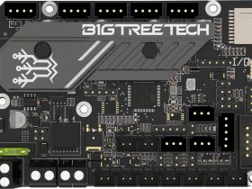
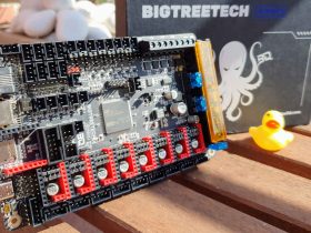
Bigtreetech has released the new SKR 3 series with two versions that include many improvements and novelties that will surely allow us to squeeze our printers to the maximum.

If you need more information or help do not hesitate to join the SKR @SKR_board_32bits Telegram group.
We remind you that you have more help guides in our Telegram bot @ThreeDWorkHelpBot
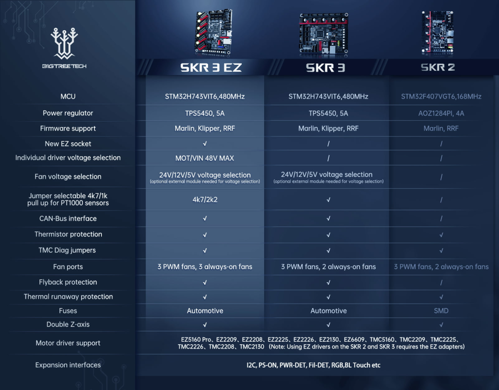
SKR 3 and SKR 3 EZ specifications
As we have advanced the new SKR 3 series of Bigtreetech has two versions of its electronics, then you have a video where you can see in summary its benefits.
Specifications common in both versions
- Multiple outputs for fans, three of them controllable with which we can optimize the use of them so that, for example, they are used as layer fans. for the hotend or for our electronics. We also have voltage selection, with a module that is not included, which allows us to select between 24v, 12v, or 5v controllable fan outputs (affects all fan outputs the selected voltage)

- Up to 5 drivers, which gives us great versatility for electronics of this size. Being able to have a real double Z in separate drivers, everything that has double motor output to one of the drivers, have double extrusion, or even to have it as a backup in case any of the others fails now is not a problem.
- Connectivity, we can use USB or CAN connections to our liking allowing greater flexibility. In the case of using CAN we have two connections, one using the USB connector and another using the 6-pin XH2.54
- Protections, if its sister the SKR 2 already had multiple protections with this SKR 3 are still maintained and improved as in the case of thermistor inputs.
- DFU mode, which will provide us with an alternative and useful way to update our SKR 3
- Support PT1000, now we will not need any external module to be able to use this high-capacity thermistor

- DCDC 5v, the inclusion of a DCDC TPS5450-5A allows us to maintain an output current of 5A, up to peaks of 6A, perfect to power our Raspberry Pi.
It is important to remember that feeding our Raspberry Pi by GPIO is not always advisable depending on the model since they do not have adequate protections for voltage / current filtering.
On the other hand, this DCDC shares the 5A with all the 5v connectors of the electronics that cover, among others, TFT, Servo, RGB, etc …
- Universal and modular WiFi, with the main objective to be used in RRF firmware we have universal WiFi support being able to choose between different controllers such as ESP12S, ESP-07, or ESP32.
- MCU, both SKR 3 and SKR 3 EZ use the same processors… an ARM Cortex-M7 CPU STM32H743VIT6 at 480MHz (and mounted on its older sisters BTT Octopus and Octopus Pro) or ARM Cortex-M7 CPU STM32H723GT6 a 550MHz. Those MCU are fully compatible with Marlin, Klipper, and RepRap.

- EEPROM, has a dedicated EEPROM chip allowing more space for firmware.
Differences between SKR 3 and SKR 3 EZ:
- Different sizes, while the SKR 3 has a size of 110*85mm the SKR 3 EZ has dimensions of 109.7*98mm.
- Compatibility with motors / HV drivers (high voltage), the SKR 3 supports motors from 12v to 24v… on the other hand, the SKR 3 EZ allows, adjusting a jumper, to work with motors from 12v to 48v something that can increase the performance of our machine in terms of printing speed.
- Normal fans are not controllable, while the SKR 3 has two connectors for normal non-controllable fans the SKR 3 EZ has 3 of these connectors.
- EZ drivers, the new EZ drivers as we will detail later have many advantages when using a new package. In the case of the SKR 3 to be able to use EZ drivers an adapter is necessary, on the other hand, the SKR 3 EZ has an exclusive socket for them.

Main advantages over SKR 2:
If we are considering renewing our electronics and we have doubts about selecting the great SKR 2 or some version of the new SKR 3 series we list some differences to help you decide the most appropriate in your case:
- The new SKR 3 series has a very powerful 480MHz MCU while normally the SKR 2 mounts a 168MHz MCU. This extra power is especially important in the case that we use firmware such as Marlin or Reprap.
- In case you want to improve your machine with HV drivers/motors (up to 48v) only the SKR 3 EZ will give you native support for them.
- Work with technical filaments is usually the most common use of PT1000 thermistors, in this case, the SKR 3 series has support for them without additional electronics.
- If you are one of those who use or plan to use CAN the SKR 3 series has more native support options.
Drivers EZ
Along with the new SKR 3 series, Bigtreetech has presented a new range of EZ drivers that are characterized by a new totally revolutionary format and that, according to Bigtreetech, will allow multiple improvements in the handling and use of these components.
Bigtreetech has released seven versions of its drivers in EZ format to cover a wide range of machines: EZ5160 Pro, EZ2208, EZ2209, EZ2130, EZ2225, EZ2226, and EZ6609. All of them use TMC drivers which are today a standard in quality and reliability in 3D printing.

In addition, its compact design, which allows the design of powerful and more compact boards, has an integrated 2-in-1 heat sink that improves the temperature and dissipation airflow improving driver performance.

On the other hand and thanks to its design does not have pins like the traditional ones reducing the risk of damaging the drivers during their manipulation something that according to Bigtreetech affects 40% of users.
In case we are interested in changing our drivers but our electronics do not have sockets compatible with EZ drivers Bigtreetech has thought of everything with adapters that allow you to use them.

Where to buy the SKR 3?
You can buy the SKR 3 or SKR 3 EZ directly from Bigtreetech Store, you can buy from other marketplaces like Amazon or Aliexpress.
The next table will show you some direct access to these marketplaces:
If you use the purchase links, the price of the product will be the same as if you access it normally, but 3DWork will have a small commission. Something that will help us support the project and continue generating content.
Connections
If something has accustomed us Bigtreetech is to have a complete arsenal of connections to get the most out of their electronics and how could it be otherwise the SKR 3 series is up to the task.
SKR 3 Series Diagrams and Schematics
We attach some diagrams of the SKR 3 series that will be very helpful in the installation/configuration:
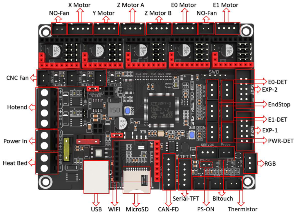
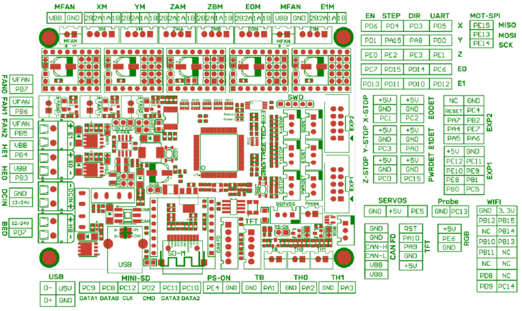
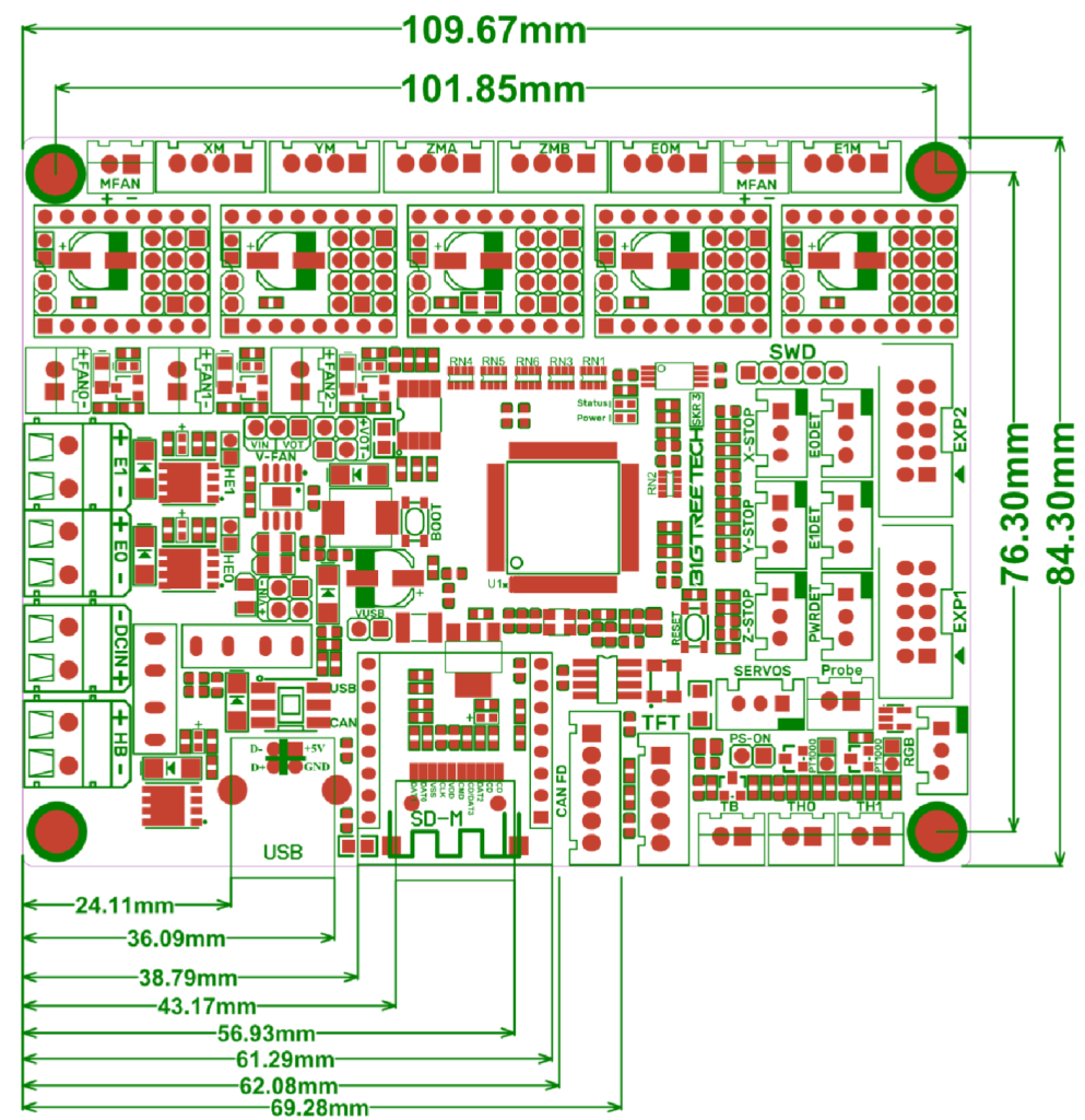
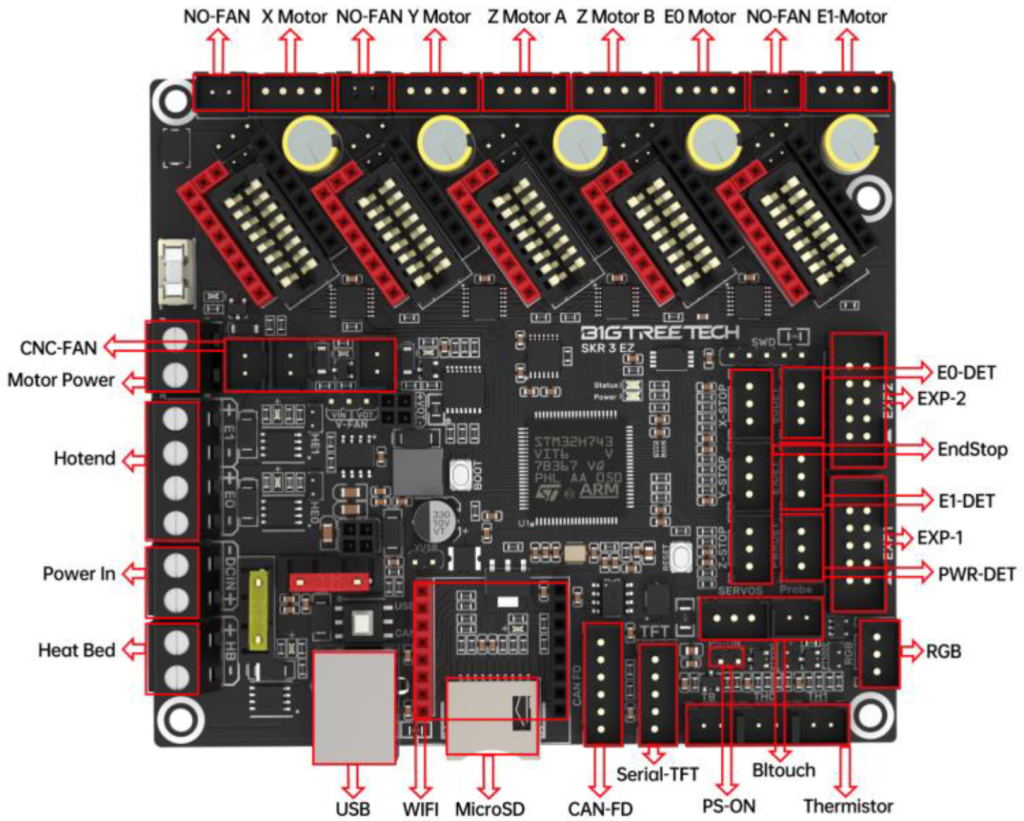
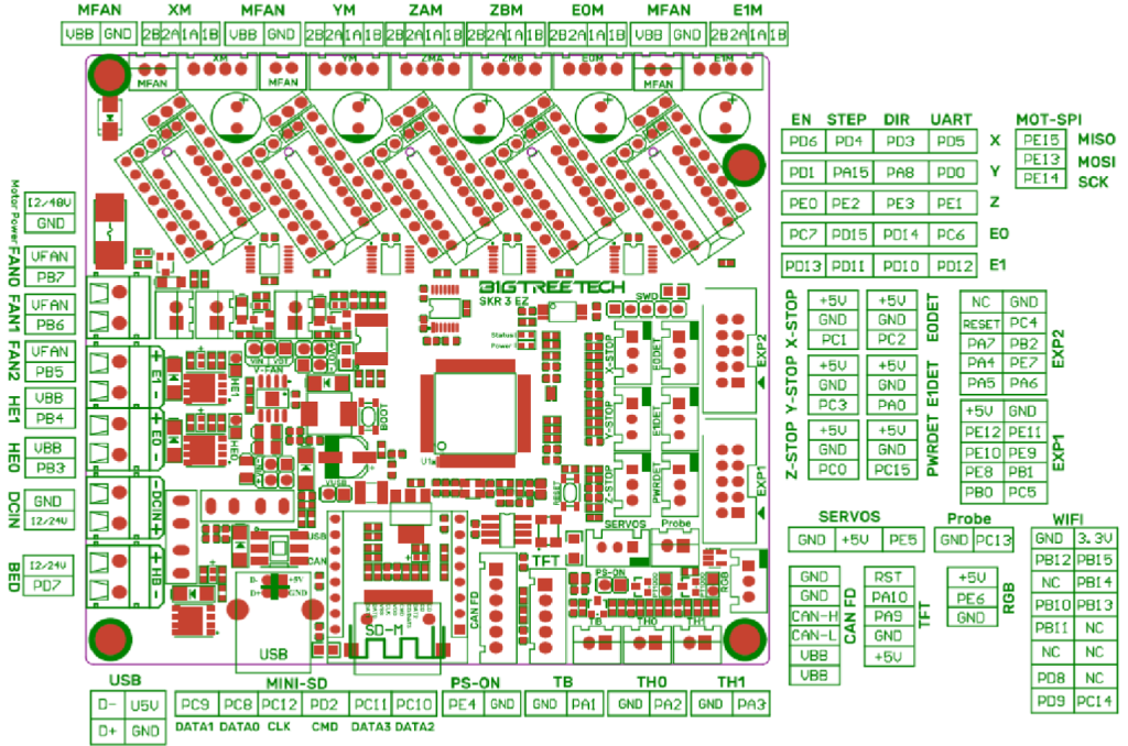
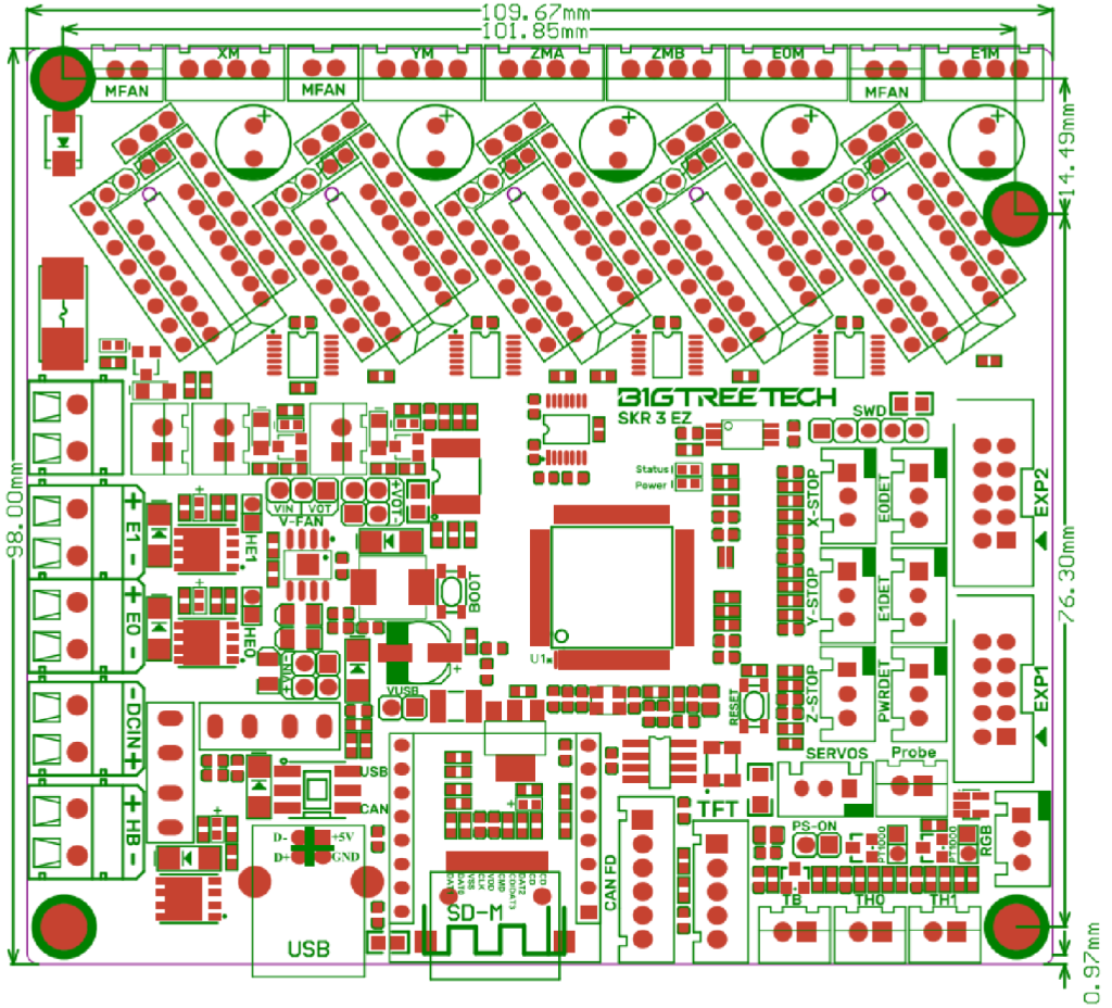
Lorem ipsum dolor sit amet, consectetur adipiscing elit. Ut elit tellus, luctus nec ullamcorper mattis, pulvinar dapibus leo.
Lorem ipsum dolor sit amet, consectetur adipiscing elit. Ut elit tellus, luctus nec ullamcorper mattis, pulvinar dapibus leo.
Basic connections
We are going to review the basic connections that we have to take into account to start up our SKR 3.
Power
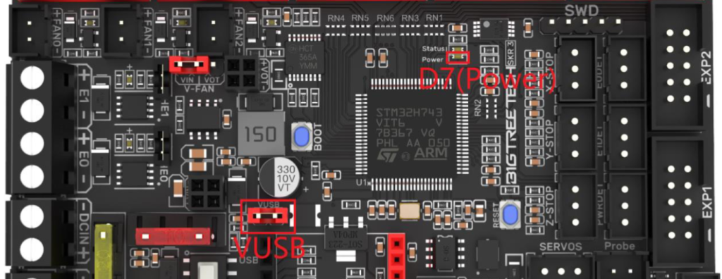
We can power our SKR 3 in two ways, depending on what we want to do with it, either from an external power supply that will be the default way or by USB in those cases that we use for basic electronics tests or firmware loading.
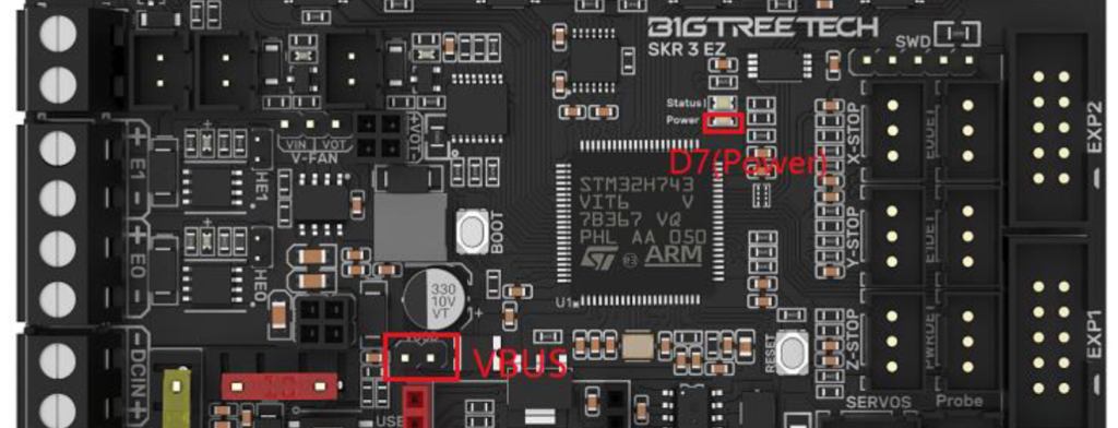
To select one way or another we will do it by means of a jumper in the VUSB pins of the electronics… with the jumper we will tell the electronics that its power is by USB.
We remind you again that in USB charging certain functions are NOT available such as moving motors, communication with intelligent drivers, heaters, etc …
Lorem ipsum dolor sit amet, consectetur adipiscing elit. Ut elit tellus, luctus nec ullamcorper mattis, pulvinar dapibus leo.
Lorem ipsum dolor sit amet, consectetur adipiscing elit. Ut elit tellus, luctus nec ullamcorper mattis, pulvinar dapibus leo.
In case the electronics get the correct power the D7 LED will light up (red), if it does not light up check the correct installation of the cables and that the fuses (yellow and red) are fine.
Drivers
The SKR 3 is compatible with a wide variety of drivers and depending on these we can use them in different modes in case they are UART / SPI or intelligent.
Step/Dir mode (STANDALONE)
In this mode the driver is used in “dumb” mode in which the electronics/firmware cannot exchange information or dynamically adjust it according to needs.
Normally we will use this mode for drivers of the type A4988, DRV8825, LV8729, etc …
or those that do not have options to be used in UART/SPI mode.
In this mode we have to configure the MS0-MS2 jumpers according to the specifications of our drivers and needs. It is important to indicate in the firmware that we are going to use this mode!!

The SKR 3 EZ does not have MS0-MS2 pins and this configuration is done directly in the electronics firmware.
UART/SPI mode
Today it is more than advisable to use drivers in UART / SPI mode which allows obtaining a better performance of the driver and the machine in addition to giving us access to some advantages such as the adjustment of the current of the motors, sensorless or other advanced functions directly from the firmware.
Depending on whether our driver will support UART or SPI, if you need more information about UART and SPI we advise you to read the TMC driver guide.
UART-compatible drivers are usually the most widespread today for low-end or mid-range machines due to their contained cost and high performance.
We usually have the TMC2208, TMC2209, and TMC2225 identical to the TMC2209 with another package that improves the driver’s cooling.
To indicate to our electronics that we are using drivers in UART mode we just have to place the driver as you see in the following screenshots.

Normally the SPI mode is restricted to medium/high-end drivers such as the TMC2130, TMC5160, TMC5161, etc.
To indicate to the electronics that our drivers will use SPI we will do it by adjusting the jumpers following the following scheme.

Lorem ipsum dolor sit amet, consectetur adipiscing elit. Ut elit tellus, luctus nec ullamcorper mattis, pulvinar dapibus leo.
Lorem ipsum dolor sit amet, consectetur adipiscing elit. Ut elit tellus, luctus nec ullamcorper mattis, pulvinar dapibus leo.
On the SKR 3 EZ and using normal TMC drivers it is not possible to mix UART and SPI drivers.
While if we use EZ drivers we can do it.
It is also important to note that the SKR 3 EZ does not have jumpers for the selection of UART/SPI and this is done through the firmware.
Sensorless mode (UART/SPI only)
A very interesting functionality to reduce wiring and possible hardware failure point with limit switches sensors is the use of Sensorless.
This functionality will allow you to dispense with limit switches by making the driver itself detect the limit switch directly.
To enable this mode we will only have to place a jumper on the electronics and properly configure our firmware. We advise you to review our sensorless guide for more detail and information.


Lorem ipsum dolor sit amet, consectetur adipiscing elit. Ut elit tellus, luctus nec ullamcorper mattis, pulvinar dapibus leo.
Lorem ipsum dolor sit amet, consectetur adipiscing elit. Ut elit tellus, luctus nec ullamcorper mattis, pulvinar dapibus leo.
This mode can only be used in the case of drivers in UART/SPI that have sensorless/stallguard compatibility.
It is advisable to use only the X and Y axes.
Fans
As we already anticipated, the SKR 3 series has 3 controllable fans perfect for use in different roles, such as layer or hotend fan or electronics, or spare in case one is damaged.


Lorem ipsum dolor sit amet, consectetur adipiscing elit. Ut elit tellus, luctus nec ullamcorper mattis, pulvinar dapibus leo.
Lorem ipsum dolor sit amet, consectetur adipiscing elit. Ut elit tellus, luctus nec ullamcorper mattis, pulvinar dapibus leo.
Another interesting novelty in this SKR 3 series is the possibility, through an external SKR 3-DC MODE module to be purchased separately, to be able to select the voltage of the controllable fan outputs. Something that can be very useful in certain machines.

To be able to use this external module the first thing will be to place the fan voltage selection jumper in the VOT position, in the VIN position it will use the voltage of our power supply. Using the SKR 3-DC MODE module we can select between 5v or 12v using a jumper.

USB/CANbus modes
With the rise of the use of Klipper and as always Bigtreetech adapting to the needs of users has introduced the use of electronics by CANbus using the USB interface.
The SKR 3 series includes a button close to the USB connection that allows the configuration of the USB port for use as CANbus or normal USB.

With the button pressed the USB port is in CANbus mode and with it without being pressed in normal USB mode.
Expansion options
The new SKR 3 series has multiple dedicated connectors to improve and expand its functionalities by improving our printer with leveling sensors, filament, relay modules, UPS modules, Neopixel or RGB LED strips, etc …
Below we attach details of some of them:
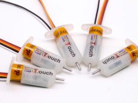
A great improvement for our printers that can make it easier for us to have the first layer as perfect as possible is the installation of a leveling sensor such as the Bltouch because it is one of the most versatile. You have detailed information in our Bltouch guide or if you prefer inductive ones in your own guide.


The electronics of the SKR 3 series have EXP connections for traditional LCDs and TFT connector for the use of serial host screens with which we have a wide range of options to have a screen in our printer.


You have more information about Bigtreetech screens in this link.
Another great improvement that can save us more than one impression is the installation of a filament sensor.
You can find more information in the following link.

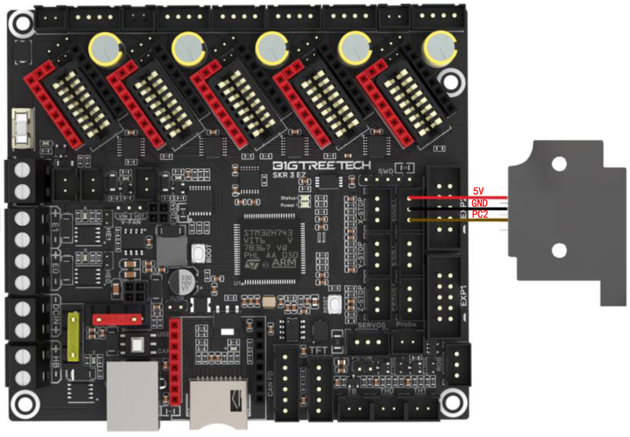
Although it is not an improvement directly in the use of the printer if it is very useful the inclusion of a controllable led strip either as the lighting of the printing area as well as event management. We encourage you to review the Neopixel guide where you will find more detailed information.


It gives us control of turning on or off our machine in a controlled way, such as turning it off once the printing is finished.


Like the relay module, el UPS allows us to perform a correct emergency shutdown especially if we use PLR (Power Loss Recovery) / restoration printing in case of power failure. You can find more detailed information in the following guide.


It is to be appreciated that Bigtreetech adds support for PT1000 thermistors that give a clear SKR 3 series approach to machines powerful in functions and options.
These advanced thermistors can allow us to work with high temperatures in a reliable way.
When we use a PT1000 thermistor we will need to connect the jumpers marked in the following captures, depending on whether we connect it in TH0 or TH1, so that the pull-up resistance of these connectors varies from 4.7K to 1K which is what these PT1000 need.

In the case of the SKR 3 EZ the pull-up resistors vary from 4.7K to 2.2K.

Lorem ipsum dolor sit amet, consectetur adipiscing elit. Ut elit tellus, luctus nec ullamcorper mattis, pulvinar dapibus leo.
Lorem ipsum dolor sit amet, consectetur adipiscing elit. Ut elit tellus, luctus nec ullamcorper mattis, pulvinar dapibus leo.
Firmware
As almost all Bigtreetech boards pay special attention to maximizing compatibility with the most popular firmware, in this case, support for Marlin, Klipper, or RRF ensures we can use this board in virtually any 3D printing environment.
Marlin
We advise you to follow our guide to “cook” your own Marlin that we have in the /Marlin section of our help bot in Telegram @ThreeDWorkHelpBot
You can find the sources of the official firmware of Bigtreetech here.
platformio.ini

In this file we must indicate the chipset that our board has, so we must look at the beginning of the file for the value “env_default” and change it to the following in the event that our board has an ARM Cortex-M7 CPU STM32H743VIT6:
default_envs = STM32H743Vx_btt

In case we have MCU STM32H723GT6:
default_envs = STM32H723VG_btt
Marlin/configuration.h

We advise you to add a comment to any line that we modify since later it will be much easier for us to find our modifications. For this we can add:
... // 3DWORK ...
We will start by defining our MOTHERBOARD which, like we did the platform.ini tells us the type of chipset that our board carries and that allows Marlin to use one pin configuration or another.
If we use Marlin 2.0.9.x:
#ifndef MOTHERBOARD
  #define MOTHERBOARD BOARD_BTT_SKR_3 // 3DWORK SKR3
#endif
If Marlin 2.1.x:
#ifndef MOTHERBOARD
  #define MOTHERBOARD BOARD_BTT_SKR_V3_0 // 3DWORK SKR3
#endif
#ifndef MOTHERBOARD
  #define MOTHERBOARD BOARD_BTT_SKR_V3_0_EZ // 3DWORK SKR3
#endif
Lorem ipsum dolor sit amet, consectetur adipiscing elit. Ut elit tellus, luctus nec ullamcorper mattis, pulvinar dapibus leo.
Lorem ipsum dolor sit amet, consectetur adipiscing elit. Ut elit tellus, luctus nec ullamcorper mattis, pulvinar dapibus leo.
We will correctly configure the SERIAL and BAUDRATE for this machine something key for the correct functioning of our TFT, USB or WIFI connection.
#define SERIAL_PORT 1 // 3DWORK SKR3
...
#define BAUDRATE 115200 // 3DWORK SKR3
...
#define SERIAL_PORT_2 -1 // 3DWORK SKR3
...
#define SERIAL_PORT_3 3 // 3DWORK SKR3
We will define the number of extruders and the diameter of the filament used by our printer which basically indicates the diameter of it. Normally printers use filament of 1.75 and in relation to the number of extruders, the most normal is to have 1.
// This defines the number of extruders
// :[0, 1, 2, 3, 4, 5, 6, 7, 8]
#define EXTRUDERS 1

// Generally expected filament diameter (1.75, 2.85, 3.0, ...). Used for Volumetric, Filament Width Sensor, etc.
#define DEFAULT_NOMINAL_FILAMENT_DIA 1.75
Thermistors, in these variables we will indicate which thermistors we have, we advise you to identify which is yours or fail to use one of value 1 that is usually the most normal.
It is very important to indicate the correct type of thermistor so that the measurements that Marlin receives are correct to avoid extrusion problems and/or reading failures.
In the case that we want to deactivate or activate the hotbed, we will comment on or activate the thermistor of the bed, in this way Marlin knows if he has a hotbed or not.
In our example and for this board we will use a hotend and a hotbed with a standard temperature sensor.
#define TEMP_SENSOR_0 1 // 3DWORK SKR3 TE0
#define TEMP_SENSOR_1 0
#define TEMP_SENSOR_2 0
#define TEMP_SENSOR_3 0
#define TEMP_SENSOR_4 0
#define TEMP_SENSOR_5 0
#define TEMP_SENSOR_6 0
#define TEMP_SENSOR_7 0
#define TEMP_SENSOR_BED 1 // 3DWORK SKR3 TB
#define TEMP_SENSOR_PROBE 0
#define TEMP_SENSOR_CHAMBER 0
#define TEMP_SENSOR_COOLER 0
Remember that this plate has support for 2 extruders and hotbed so in case of using them, we must activate the correct type in each of them.
In the case that we use a PT1000 thermistor, which this SKR 3 support natively, we must indicate that it is of type 1010 (PT1000 + 1K pull-up).
PID/MPC, another very important part is the PID/MPC of which you can get more detailed information in the /Calibration/Initial Calibration section of our help bot in Telegram @ThreeDWorkHelpBot or in our calibration guide.
Basically, the PID/MPC helps Marlin to properly control the temperature without having large fluctuations.
In the case of using up to version 2.0.9.x we will enable PID as a temperature control system in addition to the adjustment options from the screen of our printer if we have it:
#define PIDTEMP // 3DWORK PID
...
#define PIDTEMPBED // 3DWORK PID
...
#define PID_EDIT_MENU // 3DWORK PID
...
#define PID_AUTOTUNE_MENU // 3DWORK PID
In the case that we use version 2.1.x we advise you, for the hotend, to use the new MPC since it is more intelligent and adaptable than the traditional PID:
//#define PIDTEMP          // See the PID Tuning Guide at https://reprap.org/wiki/PID_Tuning
#define MPCTEMP        // ** EXPERIMENTAL **
#define MPC_HEATER_POWER { 40.0f }                  // (W) Heat cartridge powers.
#define MPC_TUNING_POS { X_CENTER, Y_CENTER, 1.0f } // (mm) M306 Autotuning position, ideally bed center at first layer height.
#define MPC_EDIT_MENU                             // Add MPC editing to the "Advanced Settings" menu. (~1300 bytes of flash)
#define MPC_AUTOTUNE_MENU                         // Add MPC auto-tuning to the "Advanced Settings" menu. (~350 bytes of flash)
ENDSTOPS or limit switches, it is important to verify when we make an electronic change and turn on for the first time that the logic of the limit switches is correct using the M119 command from a terminal such as Pronterface… this is OPEN in a normal state and TRIGGERED when pressed. We can reverse this logic by changing:
#define X_MIN_ENDSTOP_INVERTING false // Set to true to invert the logic of the endstop.
#define Y_MIN_ENDSTOP_INVERTING false // Set to true to invert the logic of the endstop.
#define Z_MIN_ENDSTOP_INVERTING false // Set to true to invert the logic of the endstop.
#define X_MAX_ENDSTOP_INVERTING false // Set to true to invert the logic of the endstop.
#define Y_MAX_ENDSTOP_INVERTING false // Set to true to invert the logic of the endstop.
#define Z_MAX_ENDSTOP_INVERTING false // Set to true to invert the logic of the endstop.
#define Z_MIN_PROBE_ENDSTOP_INVERTING false // Set to true to invert the logic of the probe.
On the other hand and although it is normal for machines to perform the home in MIN (lower left corner) instead of MAX (upper right corner), using HOME_DIR for this change -1 (MIN) 1 (MAX), we must remember that in the case of changing the logic enable the corresponding limit switches:
#define USE_XMIN_PLUG
#define USE_YMIN_PLUG
#define USE_ZMIN_PLUG
//#define USE_XMAX_PLUG
//#define USE_YMAX_PLUG
//#define USE_ZMAX_PLUG
Remember that if you have TMC drivers in UART mode you can use them if the driver supports it, the use of SensorLess that will allow you to dispense with physical limit switches by freeing components and cables.
You can find information on how to activate SensorLess in our guide to Marlin.
In any case, here is a brief information on how to enable it:

It is important to adjust the sensitivity to adjust it to our machine.
Drivers, as we have already mentioned, this board has 5 sockets for drivers supporting different types of drivers and their configurations.
In our example we will use a TMC2209 in UART mode (intelligent), with independent double Z and a single extruder:
#define X_DRIVER_TYPE  TMC2209 // 3DWORK DRIVERS
#define Y_DRIVER_TYPE  TMC2209 // 3DWORK DRIVERS
#define Z_DRIVER_TYPE  TMC2209 // 3DWORK DRIVERS
//#define X2_DRIVER_TYPE A4988
//#define Y2_DRIVER_TYPE A4988
#define Z2_DRIVER_TYPE TMC2209 // 3DWORK DRIVERS
//#define Z3_DRIVER_TYPE A4988
//#define Z4_DRIVER_TYPE A4988
#define E0_DRIVER_TYPE TMC2209 // 3DWORK DRIVERS
SKR 3 series supports different modes for drivers in STANDALONE mode as in UART/SPI mode.
– For UART/SPI mode we will take from the list the model of our driver
– For STANDALONE mode we will take the model of our driver but finished in _STANDALONE

STEPS or motor steps, all values will indicate to Marlin the motor steps to make movements. In this example we will use those that an Ender printer carries by default, in any case again we refer you to the section /Calibration / Initial Calibration of our help bot in Telegram @ThreeDWorkHelpBot or here for the process calibrate these steps for our extruder and axes of movement.
#define DEFAULT_AXIS_STEPS_PER_UNIT { 80.00, 80.00, 400.00, 93 } // 3DWORK pasos para Ender3 ejes X, Y, Z,Extrusor
S_CURVE_ACCELERATION, this functionality offers a great improvement in print quality as it smooths acceleration or deceleration when the print head is in motion.
#define S_CURVE_ACCELERATION // 3DWORK MEJORAS
Important note!!!
is that depending on our version of Marlin and if we use Linear Advance are not compatible.
In the /Calibration/Initial Calibration section of our help bot in Telegram @ThreeDWorkHelpBot or in our calibration guide, you can find more detailed information about Linear Advanced
PROBE or leveling sensor, we have already commented there is a detailed guide on how to install a BLTouch sensor we will perform a review of the most important parts to take into account in case we want to install a leveling sensor, something very advisable to ensure that our prints always have the first layer as perfect as possible.
We will start by indicating where our leveling sensor is connected, in this case, we will connect it to the final stroke connector of Z-
#define Z_MIN_PROBE_USES_Z_MIN_ENDSTOP_PIN // 3DWORK PROBE
BLTouch or Inductive sensor type, there are different types of sensors. Depending on the used we must de-comment one or the other.
Inductive type:
#define FIX_MOUNTED_PROBE // 3DWORK PROBE
BLTouch type:
#define BLTOUCH // 3DWORK PROBE
Sensor offsets, it is very important to tell Marlin where exactly our leveling sensor is installed… we will do this by defining the PROBE OFFSET.
The Offset is the distance between the tip of the nozzle and the tip of the leveling sensor depending on where it should be positive or negative values, you can use the following graph as an example of what value to put in each case.
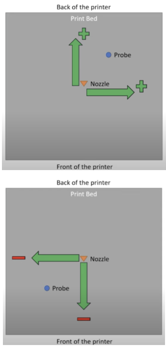
In our case and as an example our sensor is shifted to the left of the nozzle in X 30mm and 10mm in Y since it is that distance towards the bottom of the printer.
#define NOZZLE_TO_PROBE_OFFSET { -30, 10, 0 } // 3DWORK PROBE
PROBING_MARGIN (in previous versions MIN_PROBE_EDGE), it is very normal that we have glass in our printers as a printing base although personally, we like magnetic PEI sheets more than although being a little more susceptible to being marked with blows and have excellent adhesion, it does not limit the size of the bed and removing the pieces is extremely simple and fast.
In any case, whether we have a glass or another surface, it is advisable that the sensor is away from any object that may bother you during the leveling process, whether staples to fix the glass or the mismatch of the beginning and end of bed that makes the sensor unable to measure.
For this, we will use this PROBING_MARGIN in which we will tell you how many mm you have to move away from the edges of the bed.
En nuestro caso usando un BLtouch y una plataforma PEI lo dejamos por defecto.
#define PROBING_MARGIN 10 // 3DWORK PROBE
Motor direction, another very common problem when starting a printer is that the wiring of the coils of our motors does not coincide and there can be two cases:
- When the connectors of our coils are mixed, it is very easy to identify since the motor will not rotate correctly and will stumble. To solve it is advisable to check the pinout of the old plate and/or motor and compare it with that of our new plate to make sure they match
- The motor turns in the wrong direction. In this case, again we have two options… the first and advisable is to modify in Marlin the rotation of the motor and the second is to reverse the wiring of one of the motor coils
In our case we opted for the first modifying the following lines in Marlin changing the current value on the contrary… in this case, we invert the Z axis.
#define INVERT_X_DIR true
#define INVERT_Y_DIR true
#define INVERT_Z_DIR false // 3DWORK Invert Z
Print size, if we have used a generic Marlin it is important to verify that the printing dimensions are correct for our machine.
For the bed size in the example we use an Ender 3 to its maximum size, it is advisable to verify that you can physically reach these measurements and adjust it if necessary:
#define X_BED_SIZE 235 // 3DWORK BED
#define Y_BED_SIZE 235 // 3DWORK BED
...
#define Z_MAX_POS 250 // 3DWORK BED
Filament sensor, we advise you to check in the section /Improvements/Filament sensor of our help bot in Telegram @ThreeDWorkHelpBot, or in our guide you can find more detailed information about how to install and configure a filament sensor.
#define FILAMENT_RUNOUT_SENSOR // 3DWORK RUNOUT SENSOR
As with limit switches it is advisable to check with an M119 the status of the filament sensor which has to appear TRIGGERED with filament and OPEN without. In the case that it seems inverted we must play with the value of (LOW / HIGH):
#define FIL_RUNOUT_STATE LOW // 3DWORK RUNOUT SENSOR
We can also indicate the filament distance we want since the sensor detects the sensor fault in:
#define FILAMENT_RUNOUT_DISTANCE_MM 25 // 3DWORK RUNOUT SENSOR
In the event that our filament sensor works by filament flow detection (such as the BigtreeTech Smart Filament Sensor) we must enable the following:
#define FILAMENT_MOTION_SENSOR // 3DWORK RUNOUT SENSOR
Self-leveling, as we mentioned earlier in the /Leveling section of our bot @ThreeDWorkHelpBot you have more detailed information on how to activate UBL self-leveling (the most advanced and advisable for beds of a certain size or with problems) and MESH that allows you to have a mesh without sensor doing the process manually.
In any case for this example, we will enable BILINEAR.
#define AUTO_BED_LEVELING_BILINEAR // 3DWORK PROBE
It is important to tell Marlin to enable self-leveling (G29) after a homing (G28) although in current versions it is no longer necessary we advise enabling it.
#define RESTORE_LEVELING_AFTER_G28 // 3DWORK PROBE
In the case of BILINEAR we will specify the number of points to be made per mesh in the next part of Marlin (by default it has 3 points per axis, 3×3=9 check points).
if EITHER(AUTO_BED_LEVELING_LINEAR, AUTO_BED_LEVELING_BILINEAR)
// Set the number of grid points per dimension.
#define GRID_MAX_POINTS_X 3 // 3DWORK PROBE
Another function that for security we must enable is to perform a homing in the center of the bed, this helps us to two things … the first to ensure that the sensor has a surface to detect the limit switch and the second to visually verify that our Offsets are correct since the leveling sensor has to be perfectly positioned in the center of our bed.
#define Z_SAFE_HOMING // 3DWORK PROBE
EEPROM, in the EEPROM Marlin saves the configuration values of different functions so that they can be used by the system and be changed by the user without having to modify Marlin source files, compile and upload the firmware in each change. It is highly advisable to activate it and with our SKR 3, we will not have memory problems.
#define EEPROM_SETTINGS // 3DWORK EEPROM
#define EEPROM_CHITCHAT // 3DWORK EEPROM
Nozzle Park, in the example we are explaining we have added a filament sensor. For this, to work we must activate NOZZLE_PARK_FEATURE that basically allows us to “park” the print head in a safe area to make this change of filaments although if we do not have a filament sensor it is very advisable to have it active since it allows us to improve the pause functions.
#define NOZZLE_PARK_FEATURE // 3DWORK RUNOUT SENSOR
SD, if we want our Marlin to be able to read from our SD either from the board or on a screen that is compatible (note that the Touch is not) we must activate SD support.
#define SDSUPPORT // 3DWORK SD
Advanced Homing Menu, is not necessary but it is very advisable in the case of performing tests to enable this function that allows us to perform a homing separately from each axis.
#define INDIVIDUAL_AXIS_HOMING_MENU // 3DWORK HOMING
Marlin/configuration_adv.h

We have already finished the first part and now we will have to move on to the configuration of the advanced options.
Scroll and long file names, it is interesting to activate this function to be able to show the full name of the files to be printed.
Like the previous one and for it to work correctly we have to activate the following option.
#define LONG_FILENAME_HOST_SUPPORT // 3DWORK
#define SCROLL_LONG_FILENAMES // 3DWORK
SD connection, in configuration.h we enable support for SD and in configuration_adv.h we will define where Marlin will try to use that SD from.
We have three options, LCD where we will use the Marlin screen … ONBOARD where we will use the board and CUSTOM_CABLE where we will indicate that we use an external reader connected to the board
As we discussed previously, not all screens that have SD will work correctly.
#define SDCARD_CONNECTION LCD // 3DWORK SD
Fans, a great success on the part of Bigtreetech is the inclusion of 3 manageable fans.
The definition of the pin of each FAN can be found in /Marlin/src/pins/stm32h7/pins_BTT_SKR_3.h
- FAN0, in this case, we are not going to make any changes in its role since it is the layer fan and this is managed by the slicer/filleter itself to cool the filament.
- FAN1, in our example we are going to assign it to the hotend so that it is dynamically only activated when the hotend is in operation avoiding fan wear and unnecessary noise:
#define E0_AUTO_FAN_PIN FAN1_PIN // 3DWORK FAN1
...
#define EXTRUDER_AUTO_FAN_TEMPERATURE 50 // 3DWORK FAN1
#define EXTRUDER_AUTO_FAN_SPEED 255   // 255 == full speed
- FAN2, to take advantage of this arsenal of manageable fans (we can have more reusing pins of other functions such as RGB for example) assign FAN2 as a fan of dynamic electronics so that it is activated when the drivers are in use minimizing again wear and noise by the fan:
#define USE_CONTROLLER_FAN // 3DWORK FAN2
...
#define CONTROLLER_FAN_PIN FAN2_PIN // 3DWORK FAN2
...
#define CONTROLLER_FAN_EDITABLE // 3DWORK FAN2
...
#define CONTROLLER_FAN_MENU  // 3DWORK FAN2
Babystepping, an almost essential function to have is baby stepping. Babystepping allows us to adjust the height of Z during a print to manually adjust this height to our liking.
In our example, we will enable it can be activated with a double click on the button/encoder, which is always available and shows us graphic improvements in the adjustment to understand the direction of the adjustment from the screen.
#define BABYSTEPPING // 3DWORK BABYSTEPPING
#define DOUBLECLICK_FOR_Z_BABYSTEPPING // 3DWORK BABYSTEPPING
#define BABYSTEP_ALWAYS_AVAILABLE // 3DWORK BABYSTEPPING
#define BABYSTEP_ZPROBE_GFX_OVERLAY // 3DWORK BABYSTEPPING
Retries in case of failure in the leveling, another very useful function are to be able to retry the homing process in case of failure. Sometimes our leveling sensor may have a punctual failure and this function will allow us to try again a finite number of times.
#define G29_RETRY_AND_RECOVER // 3DWORK LEVELING
#define G29_MAX_RETRIES 4 // 3DWORK LEVELING
In the case of using UBL leveling this option is not supported.
ARC support, a substantial improvement in the quality of our prints and also when we print through serial devices such as TFT, Octoprint, etc … It allows simplifying the gcodes commands minimizing the number of movements and making them more fluid also avoiding a large number of retractions.
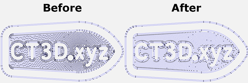
To use it we must configure our slicer to apply these changes or in the case of Octoprint we can use a plugin. As for the changes in Marlin:
#define ARC_SUPPORT // 3DWORK ARC
It is important to emphasize that in the case of enabling ARC for use it is advisable, in the case that we also have it enabled, compatibility with S_CURVE. You have more information in the calibration guide.
Advanced pause, as discussed earlier in this example we use a filament sensor. For it to work properly we have to enable ADVANCED_PAUSE_FEATURE which enables the gcode M600 command for the change of filaments.
This can be done with or without a leveling sensor and requires NOZZLE PARK for proper operation.
We will not go into the detailed configuration since you have it inside /Improvements/Sensor Filaments inside our bot or directly in the guide.
#define ADVANCED_PAUSE_FEATURE // 3DWORK M600
Configuration UART/SPI drivers, with our drivers in UART/SPI we have to correctly configure the advanced parameters that we will find in section HAS_TRINAMIC_CONFIG
Micro-steps, although we can configure from 16 to 256 micro-steps we do not advise you at all to use another value other than 16 if your machine is not well built. With these micro-steps, the definition that we could reach mechanically is practically impossible to achieve with normal printers in addition to the fact that the TMC drivers already perform the interpolation of these themselves to always offer maximum reliability and precision.
Speaking of reliability is another important aspect when it comes to micro-steps, the stepper motors that carry our printers lose torque (and steps) at high revolutions so increasing this definition of steps will exponentially increase the percentage of reliability, and therefore that our parts do not come out correctly.
In the following example, we can see how we have 16 micro-steps for our X-axis.
#if AXIS_IS_TMC(X)
#define X_CURRENT 650 // (mA) RMS current
#define X_CURRENT_HOME X_CURRENT
#define X_MICROSTEPS 16 // 0..256
#define X_RSENSE 0.11
#define X_CHAIN_POS -1
#endif
Another important value of the previous values is that of CURRENT where we will adjust the current of our motors. You can also adjust them from the LCD from Settings/Advanced/TMC along with other options that we will explain below.
STEALTHCHOP, it is important to enabling it if we want our motors to be “silent” because if they will not be running in SpreadCycle mode that is the power mode.
#define STEALTHCHOP_XY // 3DWORK DRIVERS
#define STEALTHCHOP_Z // 3DWORK DRIVERS
#define STEALTHCHOP_E // 3DWORK DRIVERS
Although it is rare some extruders may work better with StealthChop mode disabled. If this is our case we will comment on the following line.
//#define STEALTHCHOP_E // 3DWORK DRIVERS
CHOPPER TIMMING, is used by StealthChop for the synchronization of signals to the engines. This has to match the voltage used in our printer, in the case of Ender 3, and usually in all printers at 24v.
#define CHOPPER_TIMING CHOPPER_DEFAULT_24V // 3DWORK DRIVERS
Monitor Status, this function allows Marlin to control in detail all the parameters of the drives to be able to adjust, for example, their temperature to avoid more serious problems.
#define MONITOR_DRIVER_STATUS // 3DWORK DRIVERS
Hybrid Threshold, another interesting function is Hybrid Threshold which allows Marlin to switch between StealthChop (silence) or SpreadCycle (power) dynamically based on the speed of movements.
#define HYBRID_THRESHOLD // 3DWORK DRIVERS
#define X_HYBRID_THRESHOLD 100 // [mm/s]
#define Y_HYBRID_THRESHOLD 100
#define Z_HYBRID_THRESHOLD 15
In our case we use the values indicated for an Ender that is 100mm / s for X Y and 15 for Z although we can adjust it to our needs.
Although it is an interesting function we do not advise you to enable it or at least to some thresholds used during printing since it can introduce, the change between one mode or another, inaccuracies in the movements, and affect our impressions.
TMC Debug, in this case, is a requirement of MONITOR_DRIVER_STATUS that we must enable and will allow us to have accessible the M122 command very useful to obtain advanced information on the status and configuration of our drivers.
#define TMC_DEBUG // 3DWORK DRIVERS
In the case that we use drivers in SPI we must review the section TMC_USE_SW_SPI in configuration_adv.h
Expansions configurations
As we explained earlier, the SKR 3 has different expansion options with different modules. Here’s how to configure these:
Having a filament sensor in our machine is interesting to not lose some prints if we did not make a calculation of the use and availability of filament.
We already indicated in the section expansion options how to connect the filament sensor, now we are going to tell you how to configure it in Marlin.

#define FILAMENT_RUNOUT_SENSOR // 3DWORK RUNOUT SENSOR
...
#define FIL_RUNOUT_ENABLED_DEFAULT false // 3DWORK RUNOUT SENSOR
#define NUM_RUNOUT_SENSORS   1 // 3DWORK RUNOUT SENSOR
#define FIL_RUNOUT_STATE     LOW // 3DWORK RUNOUT SENSOR
#define FIL_RUNOUT_PULLUP // 3DWORK RUNOUT SENSOR
In the case that we use an intelligent filament sensor, with detection of assting or filament breakage, such as the Smart Filament Sensor from Bigtreetech:
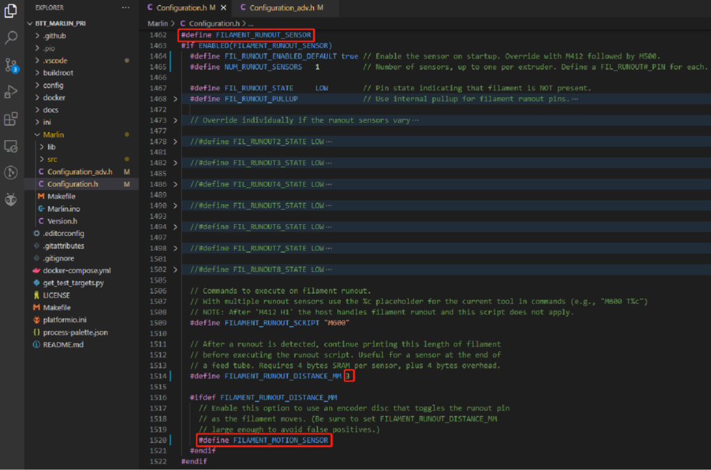
#define FILAMENT_RUNOUT_DISTANCE_MM 3 // 3DWORK RUNOUT SENSOR
...
#define FILAMENT_MOTION_SENSOR // 3DWORK RUNOUT SENSOR
We will also need to have NOZZLE_PARK although if we follow the previous Marlin configuration guide we will already have it enabled, although in the case of having a sensor it is advisable to modify the coordinates:

#define NOZZLE_PARK_FEATURE // 3DWORK RUNOUT SENSOR
...
#define NOZZLE_PARK_POINT { (X_MIN_POS + 10), (Y_MAX_POS - 10), 20 } // 3DWORK RUNOUT SENSOR
Another necessary function will be ADVANCED_PAUSE_FEATURE:

#define ADVANCED_PAUSE_FEATURE // 3DWORK RUNOUT SENSOR
You have more information extre in our specific guide of installation of filament sensor.
Another exciting improvement is to add to our printer an intelligent LED strip, Neopixel, which allows us to give it a unique touch and notice specific actions visually.
We already indicated in the expansion options section how to connect our led strip to our SKR 3, now we are going to tell you how to configure it in Marlin.
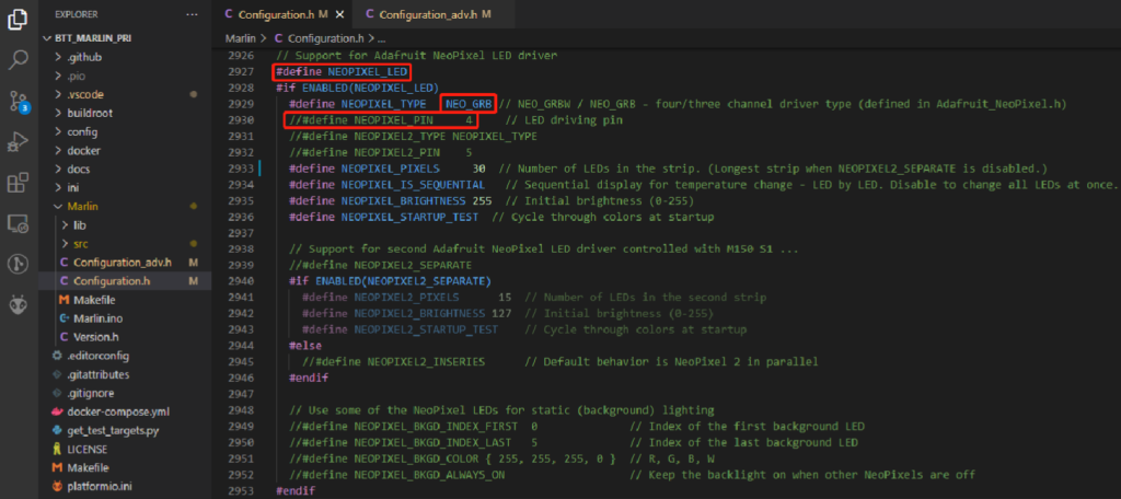
#define NEOPIXEL_LED // 3DWORKS NEOPIXEL
...
  #define NEOPIXEL_TYPE          NEO_GRBW // 3DWORKS NEOPIXEL - NEO_GRBW, NEO_RGBW, NEO_GRB, NEO_RBG, etc.
  //#define NEOPIXEL_PIN                4 // 3DWORKS NEOPIXEL definido en el fichero pins
  #define NEOPIXEL_PIXELS              30 // 3DWORKS NEOPIXEL
  #define NEOPIXEL_BRIGHTNESS         127 // 3DWORKS NEOPIXEL
  #define NEOPIXEL_STARTUP_TEST         // 3DWORKS NEOPIXEL
In the case that we have an LCD screen in Marlin emulation mode, it may be interesting to enable the control menu:
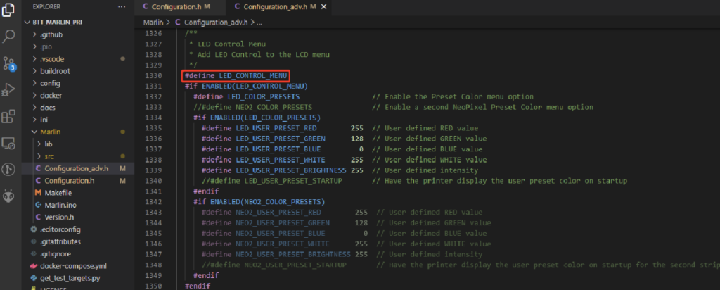
#define LED_CONTROL_MENU // 3DWORKS NEOPIXEL
Since normally our prints take several hours it is usually interesting to be able to automate the task of shutting down in the completion of printing.
Although there are different options to perform that process, either through smart plugs or other automation, we can use a relay module for shutdown control.
We already indicated in the section expansion options how to connect our relay module to our SKR 3, now we are going to tell you how to configure it in Marlin.
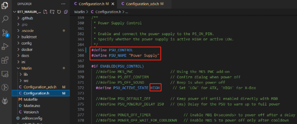
#define PSU_CONTROL // 3DWORK RELAY
#define PSU_NAME "Power Supply" // 3DWORK RELAY
#define PSU_ACTIVE_STATE HIGH // 3DWORK RELAY
The use of UPS modules together with the PLR (Power Loss Recovery) functionality or recover the impression in the event of a power failure is more than advisable in the case of wanting to take advantage of this functionality to ensure a greater % of options to be able to recover our impression without incidents.
We already indicated in the expansion options section how to connect our UPS module to our SKR 3, now we are going to tell you how to configure it in Marlin.
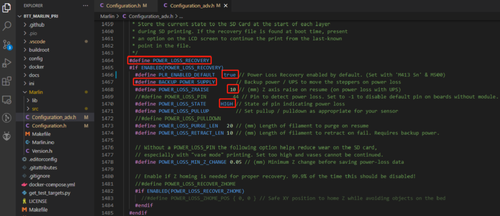
#define POWER_LOSS_RECOVERY // 3DWORK PLR
#define PLR_ENABLED_DEFAULT   false // 3DWORK PLR
#define BACKUP_POWER_SUPPLY // 3DWORK PLR
#define POWER_LOSS_ZRAISE       10 // 3DWORK PLR
#define POWER_LOSS_STATE     HIGH // 3DWORK PLR
IMPORTANT!!!
PLR mode only works with those prints that use the SD used by Marlin, and currently does not support prints launched from an external host such as Octoprint or an external TFT display.
In the case that we use PLR without a UPS module, the intensive use of the SD system can significantly reduce the useful life of the SD and generate an extra process load on our printer/electronics affecting the overall performance.
You can find more information and details in our UPS guide.
As you could read in the description of the features of the SKR 3 series we have a port to provide our printer with WiFi connectivity.
It is important to explain that this functionality is based on the ESP3D project that will allow the control of our printer via WiFi to perform some functions.
Its operation has many restrictions/limitations if we compare it with Octoprint and we would not advise the use other than to launch commands or monitor your printer from your local network.
To enable WiFi support in Marlin using an ESP8266, although it is compatible with other types of ESP, we must basically enable the SERIAL correctly… specifically UART3 on SERIAL_PORT_3.
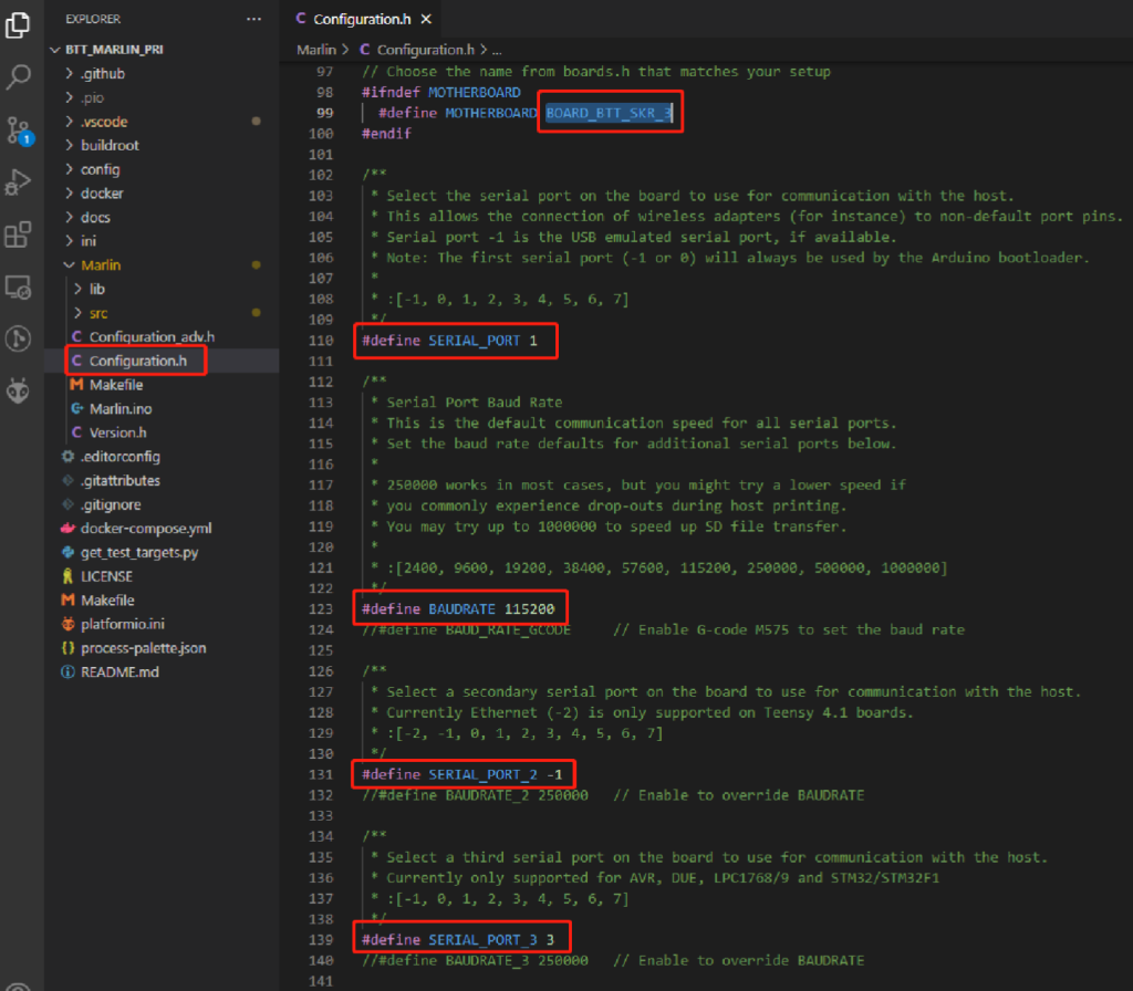
Also from configuration_adv.h we have some configuration options:

We will download the .bin or compile for our ESPxxx the ESP3D firmware by placing it in the SD with the name esp3d.bin and when rebooting/turning on the electronics if everything works as expected Marlin will apply the ESP3D firmware to our ESPxxx. We will make sure that the file in the SD goes from esp3d.bin to esp3d.cur.
From this point we should look for a WiFi AP called ESP3D and using the password 12345678 we can connect to the web interface for the configuration of the connection and access to the printer.

You have more information on theESP3D Project Wiki.
Lorem ipsum dolor sit amet, consectetur adipiscing elit. Ut elit tellus, luctus nec ullamcorper mattis, pulvinar dapibus leo.
Lorem ipsum dolor sit amet, consectetur adipiscing elit. Ut elit tellus, luctus nec ullamcorper mattis, pulvinar dapibus leo.
File pins of our SKR 3
Below you have the pins files that contain the references for this board:
- /Marlin/src/pins/stm32h7/pins_BTT_SKR_3.h
Update Marlin Firmware
In this case it is very simple and we just have to copy our firmware.bin to the root of the SD formatted in FAT32, insert the SD into the module slot and wait about 30sec for the process to finish.
Once the firmware file is finished.bin it should be renamed to firmware. CUR which we can save as a backup (remember that a compiled firmware can not be modified, that process can only be done with the source files of your firmware and recompiled).
Initial Marlin start
Now we only have to compile, adjust any error that the compiled reports and put it on our board!!!
As always we advise you to initially check the printer as follows:
- in the case of our SKR 3 check the power jumper because having it in an incorrect position will not work correctly.
- We will use the will not place the VUSB jumper for normal use of the printer powered by the printer’s power supply (12/24v)
- We will use the VUSB jumper when we have the board connected only to our computer disconnected from our printer

- check limit switches whenever possible using a terminal (Pronterface for example) with the M119 command
- in the case that we use our drivers in UART/SPI it is important to launch the M122 command from a terminal (Pronterface for example) to verify that everything works correctly. In the event that we report in all or some of our axes the ALL LOW error we can review the following points:
- We are powering our board using the printer’s power supply with the voltage selection pin in the correct position.
- That our drivers/board are prepared for UART / SPI communication since you have to place some jumpers on board and some DIY drivers may require welding a small bridge in them.
- That in our Marlin we have correctly defined the drivers as well as the UART/SPI communication addresses for our board model that we can find in configuration_adv.h looking for ADDRESS.
- individually check the homing of each of the axes of movement in the following order X and Z E and if necessary reverse the rotation of the motor
- Check that our thermistors correctly report the temperature
- Check that our bed and hotend heaters are working properly
- perform the Initial Calibration guide that you can find in our bot in the /Calibration section
Klipper
Klipper is an open-source firmware for our 3D printers that use the power of a Raspberry Pi, usually although it can be mounted on many more devices, for the control of the electronics of your printer. By doing this we can operate faster and more accurately depending on the system and hardware we have.
Something that will allow us Klipper in any case is to have a lower level control of our machine, which will also require extra knowledge/effort and greater speed when applying any change in addition to remote control of the machine first class.
It is important to emphasize that if we come from other systems Klipper may have some restrictions in terms of compatibility with components or with certain functions that we now have in our printer.
On the other hand, we have very interesting functions of control of our printer such as Pressure Advance (similar to Linear Advance of Marlin) and Input Shaper which will greatly improve the speed and quality.
Klipper basically consists of three basic components on which others can be integrated to extend the system.
- Klipper is the central component and is responsible for interpreting the gcode and control of your printer.
- Moonraker, is an API that allows linking external services with Klipper exposing print states or methods to allow other services to talk to Klipper .
- UI/Interface allows easy control of Klipper using Moonraker to interact with it.
Preparation of our Raspberry Pi
Klipper is a very versatile firmware and we can install it on almost any host/device that can run Linux.
In our examples we will always use a Raspberry Pi since it is usually the most widespread in addition to compatibility and have a moderate electric current expenditure.
First of all, we must prepare our Raspberry Pi riding Klipper, we have different options that we will describe:
- Using a Klipper distribution is the most advisable and fastest way to mount the system. We have different recommended options:
- MainsailOS, is one of the most used and highly recommended
- RatOS, is focused on Ratrig machines but if you already have knowledge of Klipper it can be very advisable even without having Ratrig machines since its modular configuration, macros and scripts are enormously useful.
- FluiddOS, is another interesting distribution to mount Klipper quickly.
- Using Kiauh, Kiauh is a set of scripts that have menus to be able to install the entire Klipper system and other extensions in a very simple way from our SSH client. It also includes some very useful tools for the maintenance/management of our Klipper.
- Manually, another option… that would not always be the most advisable depending on your knowledge … is the manual installation of all the components that Klipper needs.
We are not going to go into the detail of the installation since it is a more or less long process depending on which option we choose for the installation.
We advise you to review our Klipper installation guide.
Compiling Klipper firmware for SKR 3
Once we have the entire Klipper system mounted and access to both the UI and the terminal by SSH the next step will be the generation of the Klipper firmware for our SKR 3.
We have different options to generate this firmware:
- Using precompiled Klipper firmware that we can find in the Bigtreetech Github, although it seems the most comfortable way we do not advise it since it is very likely that sooner or later you will have to do the manual process.
To use the USART connection we have to connect the UART-TX pin of our Raspberry with the USART-RX1 pin of our board, the UART-RX pin of our Raspberry with the USART-TX1 pin of our board.
- Compiling our firmware
- We can follow the official documentation of Klipper to install it we also advise using Kiauh, Fluidd Pi or MainsaiOS to have images that greatly facilitate the installation process of all the necessary components. You can check our Klipper Guide.
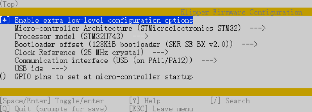
- Following the previous documentation we will go to the option of Building the micro-controller using this configuration:
- [*] Enable extra low-level configuration options
- Micro-controller Architecture = STMicroelectronics STM32
- Processor model = STM32H743
- Bootloader offset = 128KiB bootloader (SKR SE BX v2.0)
- Clock Reference = 25 MHz crystal
- If we use USB
- Communication interface = USB (on PA11/PA12)
- If we use USART1
- Communication interface = Serial (on USART1 PA3/PA2)
The klipper firmware.bin will be generated in the home/pi/klipper/out folder which if Klipper is not able to copy it directly to the SD of our SKR 3 copy manually to the SD using WinSCP or the pscp command in the CMD.
- Updating our SKR 3 to Klipper firmware will suffice to rename the firmware created/downloaded firmware-USB.bin, firmware-USART2.bin, or klipper.bin to fiwmware.bin which is the default name used by the bootloader of our SKR to make the upgrade process
Basic Klipper configuration
- Using as a reference official Klipper documentation to install it to configure Klipper we will use the SKR 3 klipper configuration .cfg as the basis for our printer.cfg which includes the correct definitions at the pine level for our SKR 3.
- You can use Klipper’s configuration documentation to enable the features that interest us most.
- If we are going to use USB to communicate Klipper with SKR 3 we will execute the following command from Klipper ls /dev/serial/by-id/*, from Kiauh we have from its menu in a quick and simple way to execute this action, to identify the correct ID of our SKR 3 and add it to our printer.cfg

[mcu]
serial: /dev/serial/by-id/usb-Klipper_stm32h743xx_41003D001751303232383230-if00
If we use USART1 to communicate we will need to modify some settings on our Raspberry Pi directly in the SD from the computer or. in the most comfortable and advisable way that is through SSH
- Delete or comment out the line console=serial0,115200 in /boot/cmdline.txt
- Add dtoverlay=pi3-miniuart-bt to the end of /boot/config.txt
- Modify the settings from [mcu] in printer.cfg to serial: /dev/ttyAMA0 and enable restart_method:command
[mcu]
serial: /dev/ttyAMA0
restart_method: command
Configuring Klipper UI for LCD/TFT
To enable the Klipper UI for LCD/TFT screens we have the following examples:
BTT TFT Emulación
BigtreeTech’s dual TFTs are all-terrain and the best screens for our printers have a perfect emulation mode for use in Klipper. To enable them we will configure the [display] section in printer.cfg as follows:
[display]
lcd_type: emulated_st7920
spi_software_miso_pin: PA14 # status led, Virtual MISO
spi_software_mosi_pin: EXP1_3
spi_software_sclk_pin: EXP1_5
en_pin: EXP1_4
encoder_pins: ^EXP2_5, ^EXP2_3
click_pin: ^!EXP1_2

[output_pin beeper]
pin: EXP1_1
Reprap Firmware
As we have mentioned, the SKR 3 supports RepRap Firmware which you can find here.
We advise you to follow the following guide for the detailed configuration of our SKR 3 in RRF.














NOT CONNECT WITH Btt tft50
Hi rzboril,
maybe if you can try to provide more information will be great.
Basically, those displays have 2 working modes:
* touch part, here you need to take into account the black cable well connected… the SERIAL and BAUDRATE from your Marlin firmware… and finally assure your TFT50 firmware is updated. You can obtain more information here https://github.com/bigtreetech/BIGTREETECH-TouchScreenFirmware
* Marlin emulation part, in this case you need to connect the EXP cables and assure your firmware has defined the correct LCD screen… you should have information on previous link provided
Regards.