The Raspberry Pad 5 from Bigtreetech looks at first glance like a 5-inch touch screen… Nothing could be further from the truth.
Raspberry Pi 5
The Raspberry Pad 5 can be an ally for many of your projects. In our case, we are going to focus on its use as a Klipper host for our printers.
On the back we see that it has a Raspberry Pi Compute Module 4, or CM4 from here on, which allows you to directly connect MCU modules with CM4 format. In addition, we also have an arsenal of connections such as HDMI port with 2K support, a GPIO, USB-C port, USB 2.0 connectors, CSI interface and even an RJ-45 Ethernet connector for connection to our wired networks.

IMPORTANT!!!
The Bigreetech CB1 module, equivalent to CM4, is not compatible in this case with the Raspberry Pad 5.
Nor does it include the RTC (Real Time Clock) battery of 3v CR1200.
As for the graphic part of the screen, we have an IPS panel with up to five simultaneous keystroke captures and a resolution of 800×480 pixels. It is also appreciated to have three buttons to control the brightness and rotation of the screen.
The Raspberry Pad 5 can be an ally for many of your projects. We are going to focus on its use as a Klipper host for our printers.
Previously we have told you that the Raspberry Pad 5 has a connector for the connection of a CM4 module, but… What exactly is a CM4?
Basically, a CM4 module is a small board that incorporates an ARM Cortex-A72, the same one used by a Raspberry Pi 4. These modules are manufactured for, as in our case with the Raspberry Pad 5, another controller that provides interfaces or functions such as USB, video outputs, etc.
Taking into account the limitations and price of Raspberry Pi, the use of these CM4 modules together with our Raspberry Pad 5 will allow us to have, for our case, a powerful Klipper host thanks to the CM4 and capable in options thanks to the Raspberry Pad 5 part of connections and screen.
Where to buy the Raspberry Pad 5?
BIQU/Bigtreetech have their own online store where you can buy the Bigtreetech Pad 5 directly. In any case, we provide you with some links to other reference stores:
If you use the purchase links, the price of the product will be the same as if you access it regularly, but 3DWork will have a small commission.
Something that will help us support the project and continue generating content.
Preparing our Raspberry Pad 5
Now that we have all the information of our Raspberry Pad 5 it is time to start preparing it to install Klipper
The first step to perform is the installation of the CM4 module which, together with the screws supplied, we will anchor in the CM4 socket of our Raspberry Pad 5
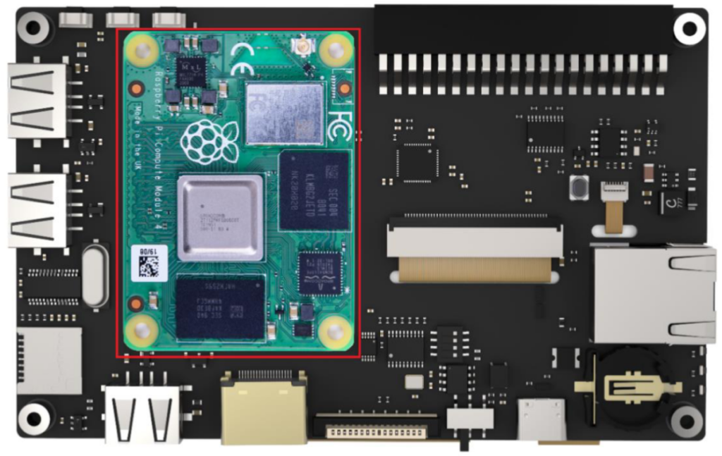
CM4 module orientation:
Continuing with the CM4 module it is important to identify what type of module we are going to use, basically we have 4 combinations with different configurations.
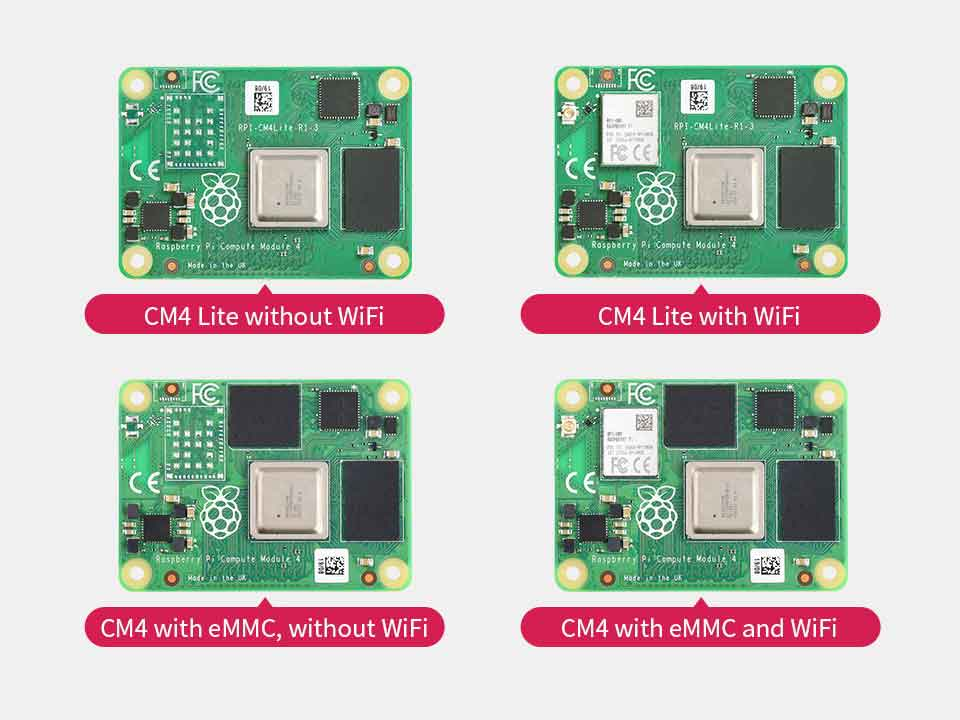

On the one hand, we have to identify if our CM4 is the version with eMMC or Lite, since it will affect the way of installing our Klipper.
Installing Klipper
Below, we detail the process to install Klipper in both CM4 Lite modules and modules with eMMC. We will use our favorite distribution MainsailOS.
For CM4 Lite modules (without eMMC)
If our module is a CM4 Lite, without eMMC, we must install our MainsailOS image using our SD:
- We will insert our SD into our computer, we advise an SD of at least 16Gb-32Gb and that has a speed of reads / writes as good as possible for a better experience.
- We will open our Raspberry Pi Imager, if you do not have it installed you can download it from here
- The first step will be to select the OS to install, where we will choose Other specific-purpose Os → 3D printing → MainsailOS and select the version that best suits our needs:


- Once you have selected our OS, the next step will be to choose our SD drive
- Before proceeding to apply the OS image to our SD, and to save you steps later, we advise you to adjust the advanced options such as enabling SSH or WiFi configuration using the gear icon


- With everything well-adjusted we will proceed to write in our SD MainsailOS


- Once the process is finished, we will insert the SD in the socket of our Raspberry Pad 5
The Raspberry Pad 5 has 3 LEDs for system diagnostics that can help us identify problems:
— BLUE, shows that our CM4 module is powered
— GREEN, the OS of our CM4 module is running
If the WiFi configuration process fails, we can put the SD back on our computer and adjust the file wpa_supplicant or you can use the raspi-config command.
For CM4 eMMC modules
In the event that our CM4 module has eMMC we must perform the installation in a different way from the previous one following these steps:
Installing the OS for Klipper in the SD will not work if our CM4 module has eMMC.
If we use Mac or Linux it will be a little more laborious to use RPIboot because we will have to compile it, from the previous link for Mac & Linux versions we have more detailed steps:
sudo apt install git libusb-1.0-0-dev pkg-config
git clone –depth=1 https://github.com/raspberrypi/usbboot
cd usbboot
make
sudo ./rpiboot
— In the case of Mac
git clone –depth=1 https://github.com/raspberrypi/usbboot-
cd usbboot
brew install libusb
brew install pkg-config
make
sudo ./rpiboot
- We will adjust the USBOTG switches and the BOOT in the positions as you see in the following image to enter BOOT mode in our CM4 module:

- We will launch RPIboot and connect our Raspberry Pad 5 via USB-C. If everything has gone correctly, we will mount our CM4 module as a unit of our computer
- We will open Raspberry Pi Imager and perform the same process to apply the image in the SD but in this case we choose our Raspberry Pad 5
- Once the installation process is finished, we will disconnect the USB-C cable to our Raspberry Pad 5
- We will change the USBOTG switches and the BOOT in the original positions
MainsailOS settings
IMPORTANT!!!
- We will connect the USB-C charging cable again and use our application from our phone, or any other that allows us to find the connected equipment in our network, to detect the IP assigned to our Raspberry Pad 5 and be able to connect by SSH
- The first thing will be to install the necessary drivers for the screen to work:
sudo wget https://datasheets.raspberrypi.com/cmio/dt-blob-disp1-cam1.bin -O /boot/dt-blob.bin
In case we want to use the HDMI connection again, we must delete the /boot/dt-blob file.bin
- Our Raspberry Pad 5 comes equipped with a USB 2.0 hub, but by default the OS of the CM4 modules can have it disabled. To enable it we will put our CM4 module in BOOT mode as we did previously, or we will place the SD on our computer to edit the config file.txt adding at the end:
dtoverlay=dwc2,dr_mode=host
- We will install KlipperScreen from our SSH terminal if it is not carried by our MainsailOS distribution
cd ~/
git clone https://github.com/jordanruthe/KlipperScreen.git
cd ~/KlipperScreen
./scripts/KlipperScreen-install.sh
We advise you to add this section at the end of your moonraker.conf:
type: git_repo
path: ~/KlipperScreen
origin: https://github.com/jordanruthe/KlipperScreen.git
env: ~/.KlipperScreen-env/bin/python
requirements: scripts/KlipperScreen-requirements.txt
install_script: scripts/KlipperScreen-install.sh
managed_services: KlipperScreen
If everything has gone well, we can access the Klipper web interface from our browser from any device on your network and access through KlipperScreen using your screen.
Los siguientes pasos serán crear tu printer.cfg, crear y aplicar el firmware Klipper a tu electrónica si no lo tiene todavía y encontrar el serial_ide para nuestro printer.cfg.











Déjanos un comentario