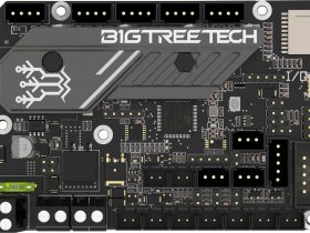
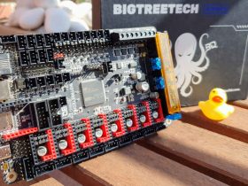
Lately the new electronic boards of the company BigTreeTech (SKR V1.4 and SKR 1.4 Turbo) are enjoying quite a notoriety within the world of 3D printing. And it is not surprising, since they have perfectly understood the “Maker” movement and have adapted to the needs of users and potential clients.
Having different sockets for all types of displays, specific BLTouch/3DTouch connectors, ease of use with TMC drivers without external wiring, specific connectors for LED strips, removable protection fuses and a few other things are just some examples of how it has targeted BigTreeTech the market quite successfully.
In fact, in our Telegram channel of 3DWork often enough people with this type of electronics enter to ask questions. So I had in mind for some time to prepare a guide to configure Marlin 2.x with SKR v1.4 / SKR v1.4 Turbo electronics + TMC2209 Sensorless drivers. And, of course, its splendid TFT35 V3.0 hybrid display, which seems to me a real virgin if I am honest.
So let’s get to it without further delay. And don’t forget to add us to our social networks (Facebook, Twitter, Instagram), this way you will support the 3DWork project.
Introduction to SKR electronics
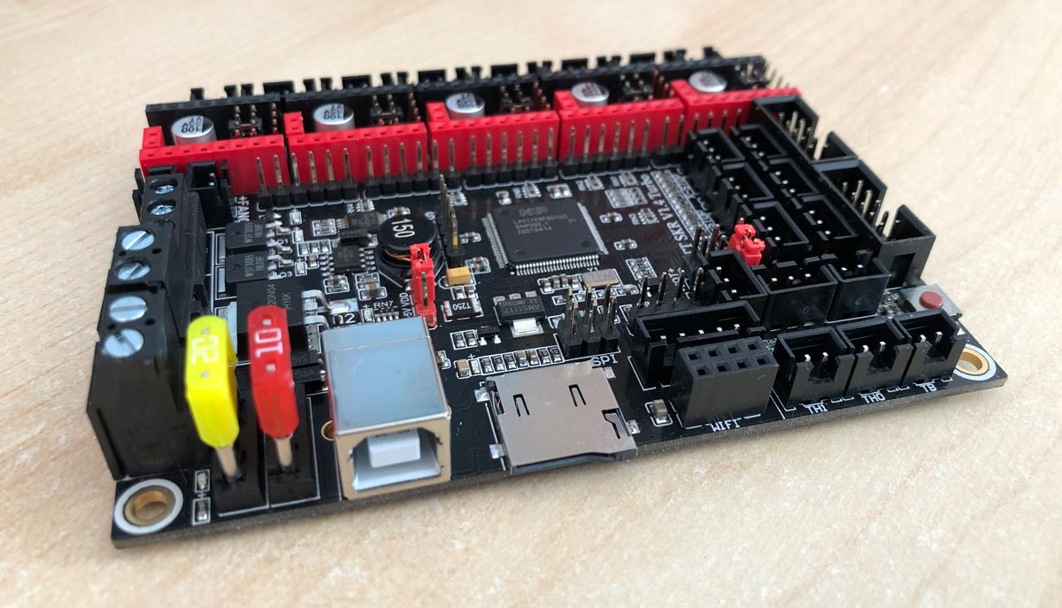
In today’s article we are going to focus on how to configure our SKR V1.4 / V1.4 Turbo electronics, along with TMC2209 Sensorless drivers and the new hybrid TFT35 V3.0 display.
Sensorless, in case you don’t know, means not putting mechanical limit switches on the X and Y axes. Modern TMC2209 drivers allow us to perform this function and save us time, money and unnecessary wiring.
In fact, if you already have these limit switches, you can use them as filament cut sensors. So at least you could give a new utility and it would not be left in the forgotten drawer.
I am aware that you may not have the same display or your drivers are different. However, even if this were the case, quite a part of the article will be useful to you, and you only have to skip the component and find your own configuration.
Also, if you feel like it, you can always visit us at our Telegram channel, and if the necessary information is not documented help us complete the article to facilitate the same process for other users.
Technical specifications and connections
SKR v1.4 and v1.4 Turbo boards have an exact size of 110 x 85mm (102 x 76mm between holes). Their architecture is ARM Cortex-M3 (CPU) and they can be powered interchangeably at 12V and 24V (5A-15A).
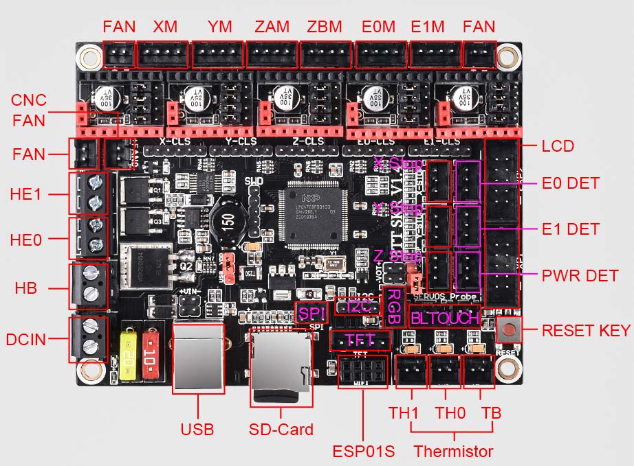
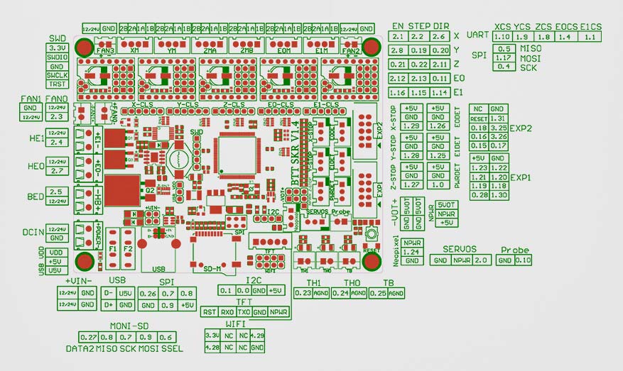
They have a connector for WiFi modules ESP-01S, can use different communication modes for their drivers (SPI, UART and STEP / DIR) and support X, Y, ZAM, ZBM, E0 and E1 motors.
Then I leave you some official images of the manufacturer where you can see all the connections and sockets of the electronic v1.4 and v1.4 Turbo.
Comparison between SKR V1.3, V1.4 and V1.4 Turbo
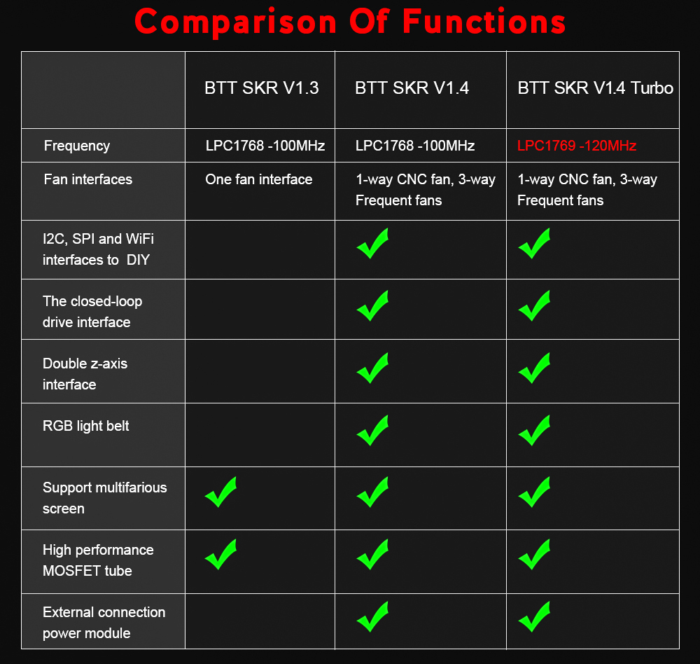
The differences are more marked when we compare a SKR v1.3 electronics with its higher versions v1.4 and v1.4 Turbo. As you can see in the image above, the latest electronics add quite interesting functions. Double interface for the Z axis, support for external power modules, support for LED strips, and some other things.
If we only compare the last two models, the only thing that differentiates the SKR v1.4 electronics from the v1.4 Turbo is that it has a superior microcontroller. In the v1.4 model we can find a 100 Mhz ARM Cortex-M3 micro, while in v1.4 Turbo the micro it presents can reach frequencies of up to 120 Mhz. This is certainly a remarkable 20% increase in process speed, which is no small feat.
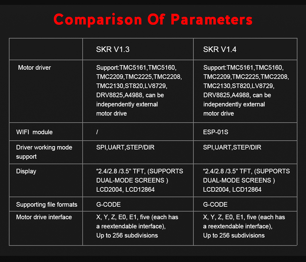
In this other table you can see another comparison on different aspects of the electronic v1.3 and v1.4 / v.14 turbo, mainly the possibility of communication via WiFi.
This requires a specific module for this task, and transmission speeds are certainly quite low. Sending a GCode of some megabytes can get you desperate, so at this point it is more advisable to use a Raspberry Pi with Octoprint for such a task.
If you do not know what Octoprint is and the possibilities it can offer you, I recommend you read the article Octoprint: Manage your 3D printer remotely with Raspberry Pi and Octopi
However, although these tables extracted from official SKR support indicate that it does not have WiFi support, this does not in any way imply that you cannot install one if you wish. It simply means that the v1.3 versions do not have a specific port to connect them to, but you could plug your WiFi module into the TFT connector and remap it into Marlin (for example).
Necessary components
Here I leave you some of the components that appear in today’s article. It is my duty to inform you that they are affiliate links to different online marketplaces online stores.
If by chance you use them, the price of the product will be the same as if you access regularly. And 3DWork will have a small commission left to help maintain this website.
| SKR v1.4 | |||
| SKR v1.4 Turbo | |||
| BTT TMC2209 v1.2 | |||
| MKS TMC2209 v1.0 | |||
| MKS TMC2209 v2.0 | |||
| FYSETC TMC2209 v3.0 | |||
| ERYONE TMC2209 v3.0 |
Or if you wish, you can use our component search engine Markets.sx, where you can compare prices in different Marketplaces (Amazon, Aliexpress, Banggood, etc.) with a single search and very easily.
Preparing the project
Visual Studio Code

Before starting to edit Marlin, I recommend that you install a good code editor. For this purpose, the ideal – and recommended by me – is that you install Visual Studio Code. Not only is it a powerful code editor, but it also has a large number of extensions, and you can even compile Marlin directly from it.
Visual Studio Code can be freely downloaded (completely free) from your project’s website at next link. And once you have edited Marlin and the necessary parameters – which you will find a little later – you can compile it and upload your new firmware to the printer.
In this article you can find more information on how to correctly compile your new Marlin firmware and upload it directly to your printer: Configure and update your 3D printer using Visual Studio Code and Platform.io
Downloading Marlin 2.x
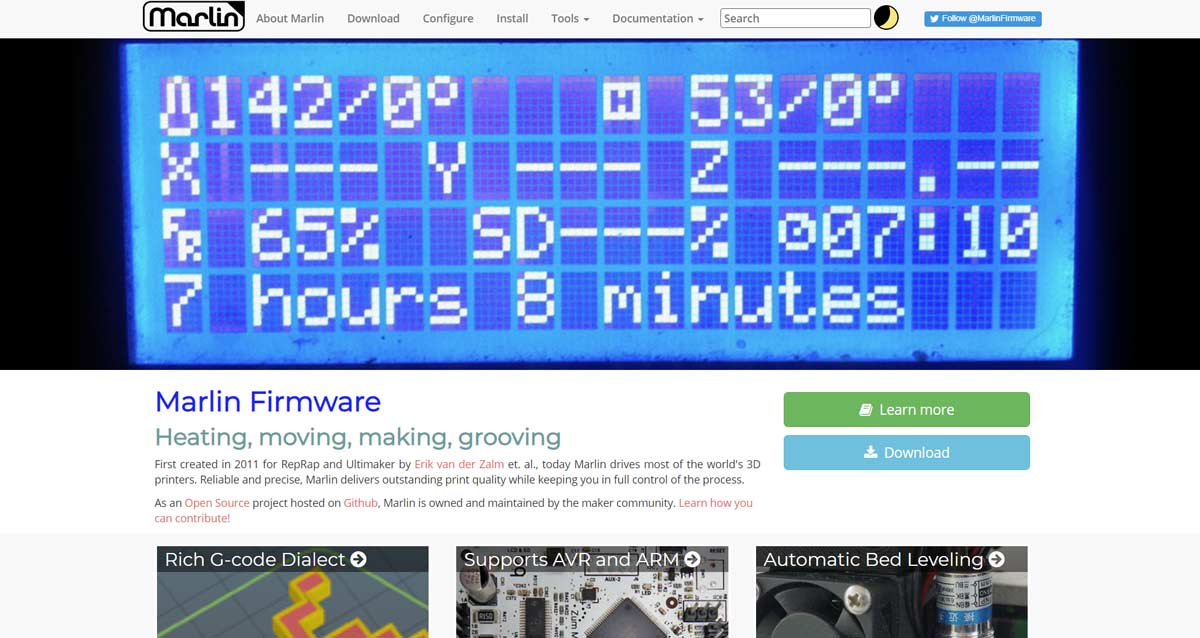
The next thing you should do, of course, is download the Marlin sources – or source code – to your computer. To do this we will go to its official website and access the download section.
Here I leave you the direct link, to that you can save some time. I usually download the firmware LATEST RELEASE, just below the word DOWNLOAD. There, click on the 2.0.x.zip link, which is the one available today for version 2.0.5.3
Please note, however, that new updates and revisions are released regularly. So it is possible that when you read this article there is a higher version and its name is different. In that case it would not be a major problem, download the latest version and that’s it.
Another option is to download the version of the manufacturer Bigtreetech, although I do not know the configuration that will be established and of course it will not adapt to the mechanics of your machine. Firmwares are available on Github at next link.
Using 3DWork Marlin Builder
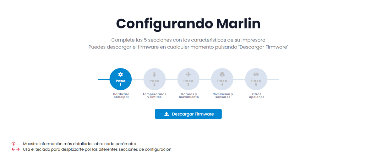
Although, in the previous section we recommend you download Marlin directly from the official page, you can also use our Marlin Builder that we prepared some time ago in 3DWork.
Marlin Builder offers you two possibilities. The first is to directly configure the firmware with the desired parameters from your browser and download it later. In this way, you will save a lot of work in this regard and then you will only have to finish configuring your SKR electronics with TMC drivers with the information in this article.
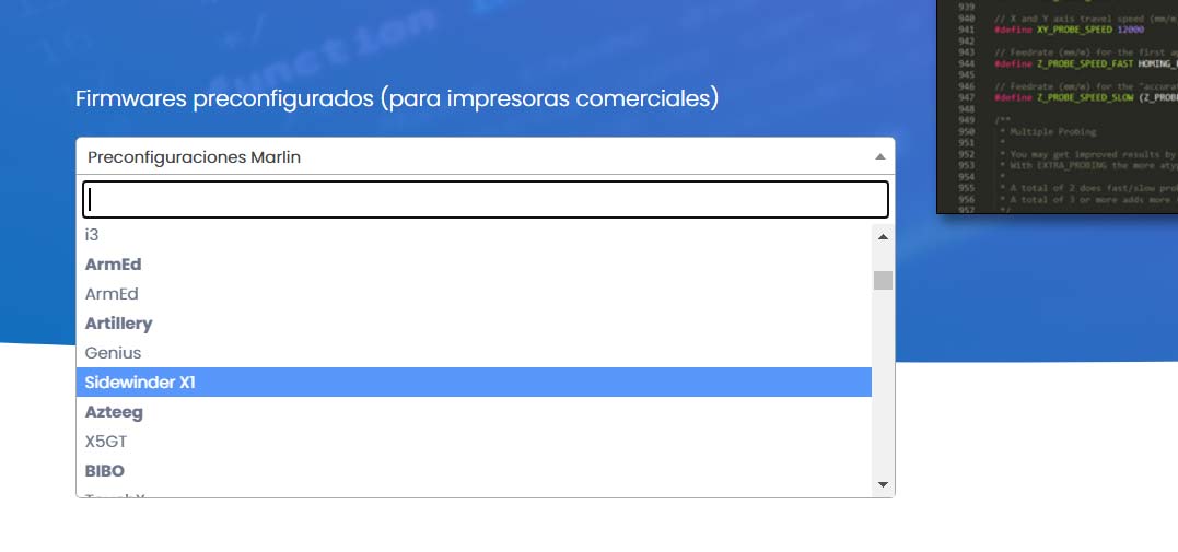
The second option Marlin Builder offers you to download a series of pre-configured firmwares officially offered by Marlin. I personally would search between manufacturers and firmwares if your printer exists and I would use it as a base, since it will be absolutely everything previously configured.
Then you just have to follow the instructions in this article and you can enjoy your new electronics quickly. You simply have to select the brand and model from a dropdown and press the download button (see image above).
Check the board supply (12V / 24V)
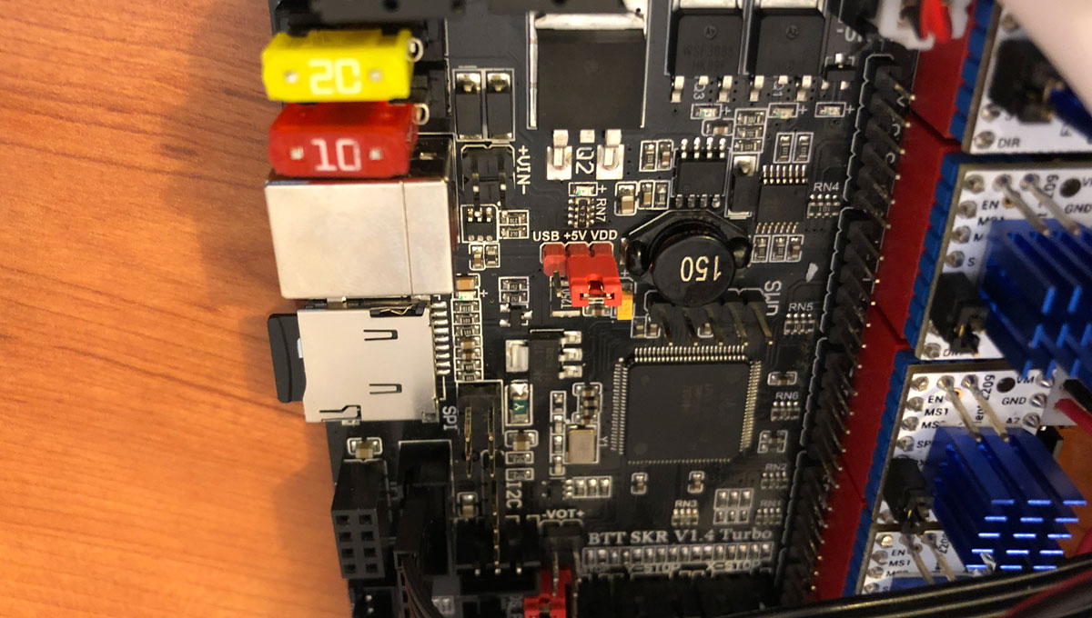
If you look closely, there is a jumper in the central part of our SKR v1.4 and v1.4 Turbo electronics that indicates the way of feeding the board.
Before connecting your electronics you must select the power that you are going to supply to your board correctly (5V USB or 12 / 24V VDD). If you are going to power the board from a USB cable, you must choose the USB option, and if you use a power supply, the VDD option.
My electronics is connected to my 24V power supply, so I choose the VDD option as you can see in the image above (click to enlarge)
Another important detail is that the SKR electronics support 12V or 24V. Regardless of the power source you use, you should always use components that match it.
If your power supply is 24V, the fans you use must be 24V (otherwise you can irreparably damage them). Probably it was not necessary to remember it but it never hurts, since there are several components to consider.
Configuring the firmware (Marlin)
Before starting with the Marlin configuration, if you are starting from scratch to prepare your new firmware, I recommend that you read this other article before: Complete guide: Set up Marlin 2.0.x from scratch and not die trying.
The reason is that in this article I am only going to explain how to configure the SKR v1.4 and SKR v.14 Turbo electronics to use all the power that the TMC2209 (Sensorless) drivers offer us, configuring themselves “intelligently” and their “hybrid” display TFT35 v3.0
The rest of the components of the printer such as the number of extruders, speeds, printer size, temperature parameters and many other things we already explained previously in the article that I indicated a few lines above (Complete guide of Marlin).
It wouldn’t make much sense deploying again all that information here as we will duplicate content without any need. Well clarified this point … Let’s start!
Modifying “Platformio.ini” file
The first file that we are going to modify is the “Platformio.ini” to indicate to our compiler what type of microprocessor we have in our electronics. If we do not indicate it Visual Studio Code you would have problems compiling our firmware.
This file is located inside the Marlin firmware, exactly in the root directory. Here you have the values depending on which of the two we are going to install on your printer.
| Electronic board type | ENV_DEFAULT |
| SKR v1.4 | LPC1768 |
| SKR v1.4 Turbo | LPC1769 |
Already knowing what values we have to use, we will edit “Platformio.ini” and in the field “env_default” we will put the chord to our electronics. In my case I have a v1.4 Turbo so I directly added “LPC1769”
[platformio]
src_dir = Marlin
boards_dir = buildroot/share/PlatformIO/boards
default_envs = LPC1769
include_dir  = Marlin
Modifying “Configuration.h” file
Once the microprocessor type of our electronics is configured in Visual Studio Code, we proceed to modify the two files that are necessary in Marlin.
We will start with the parameters to configure the communication ports (main and secondary) and the communication speed. In this last parameter I usually put 250,000bds but if you experience any problem, use 115,200bds.
/**
* Select the serial port on the board to use for communication with the host.
* This allows the connection of wireless adapters (for instance) to non-default port pins.
* Serial port -1 is the USB emulated serial port, if available.
* Note: The first serial port (-1 or 0) will always be used by the Arduino bootloader.
*
* :[-1, 0, 1, 2, 3, 4, 5, 6, 7]
*/
#define SERIAL_PORT 0

/**
* Select a secondary serial port on the board to use for communication with the host.
* :[-1, 0, 1, 2, 3, 4, 5, 6, 7]
*/
#define SERIAL_PORT_2 -1
/**
* This setting determines the communication speed of the printer.
*
* 250000 works in most cases, but you might try a lower speed if
* you commonly experience drop-outs during host printing.
* You may try up to 1000000 to speed up SD file transfer.
*
* :[2400, 9600, 19200, 38400, 57600, 115200, 250000, 500000, 1000000]
*/
#define BAUDRATE 250000
Now we are going to tell Marlin exactly what type of electronic board our printer has. I leave you a list here of the different SKR models and on your right the parameters that you must enter:
| Electronic board type | Parameter |
| SKR v1.1 | BOARD_BTT_SKR_V1_1 |
| SKR v1.3 | BOARD_BTT_SKR_V1_3 |
| SKR v1.4 | BOARD_BTT_SKR_V1_4 |
| SKR v1.4 Turbo | BOARD_BTT_SKR_V1_4_TURBO |
I have a v1.4 Turbo, so I indicate it to Marlin as follows:
// Choose the name from boards.h that matches your setup
#ifndef MOTHERBOARD
#define MOTHERBOARD BOARD_BTT_SKR_V1_4_TURBO
#endif
Then we will configure the type of driver we have and the motors on which they are mounted. We will look for the following lines and add them to it. You have a multitude of different drivers, so if yours was not TMC2209 change it for the one you are going to install.
/**
* Stepper Drivers
*
* These settings allow Marlin to tune stepper driver timing and enable advanced options for
* stepper drivers that support them. You may also override timing options in Configuration_adv.h.
*
* A4988 is assumed for unspecified drivers.
*
* Options: A4988, A5984, DRV8825, LV8729, L6470, L6474, POWERSTEP01,
*          TB6560, TB6600, TMC2100,
*          TMC2130, TMC2130_STANDALONE, TMC2160, TMC2160_STANDALONE,
*          TMC2208, TMC2208_STANDALONE, TMC2209, TMC2209_STANDALONE,
*          TMC26X,  TMC26X_STANDALONE,  TMC2660, TMC2660_STANDALONE,
*          TMC5130, TMC5130_STANDALONE, TMC5160, TMC5160_STANDALONE
* :['A4988', 'A5984', 'DRV8825', 'LV8729', 'L6470', 'L6474', 'POWERSTEP01', 'TB6560', 'TB6600', 'TMC2100', 'TMC2130', 'TMC2130_STANDALONE', 'TMC2160', 'TMC2160_STANDALONE', 'TMC2208', 'TMC2208_STANDALONE', 'TMC2209', 'TMC2209_STANDALONE', 'TMC26X', 'TMC26X_STANDALONE', 'TMC2660', 'TMC2660_STANDALONE', 'TMC5130', 'TMC5130_STANDALONE', 'TMC5160', 'TMC5160_STANDALONE']
*/
#define X_DRIVER_TYPE  TMC2209
#define Y_DRIVER_TYPE  TMC2209
#define Z_DRIVER_TYPE  TMC2209
//#define X2_DRIVER_TYPE A4988
//#define Y2_DRIVER_TYPE A4988
//#define Z2_DRIVER_TYPE A4988
//#define Z3_DRIVER_TYPE A4988
//#define Z4_DRIVER_TYPE A4988
#define E0_DRIVER_TYPE TMC2209
//#define E1_DRIVER_TYPE A4988
//#define E2_DRIVER_TYPE A4988
//#define E3_DRIVER_TYPE A4988
//#define E4_DRIVER_TYPE A4988
//#define E5_DRIVER_TYPE A4988
//#define E6_DRIVER_TYPE A4988
//#define E7_DRIVER_TYPE A4988
And to finish with the edition of the file “Configuration.h” we will edit two other very important parameters that we cannot forget. The first of them will help us to activate the Marlin emulation on our display.
This means that if you are using a “hybrid” display, you can change from TouchMode to marlin (text) mode by pressing the main button for 3 seconds. It is an incredible function, I personally hate touch screens and I have always preferred the original Marlin menu, so it goes to my hair as they say.
The second parameter will allow us to support eeprom storage on our printer, it is also essential to activate it.
//
// RepRapDiscount FULL GRAPHIC Smart Controller
// http://reprap.org/wiki/RepRapDiscount_Full_Graphic_Smart_Controller
//
#define REPRAP_DISCOUNT_FULL_GRAPHIC_SMART_CONTROLLER
/**
* EEPROM
*
* Persistent storage to preserve configurable settings across reboots.
*
*   M500 - Store settings to EEPROM.
*   M501 - Read settings from EEPROM. (i.e., Throw away unsaved changes)
*   M502 - Revert settings to "factory" defaults. (Follow with M500 to init the EEPROM.)
*/
#define EEPROM_SETTINGS     // Persistent storage with M500 and M501
Modifying “Configuration_adv.h” file
It is the turn of the file “Configuration_adv.h”. If you have done your homework and read our previous article on how Configure Marlin 2.x from scratch, you will know that this file stores more advanced configurations on Marlin, as well as more experimental or in development ones.
The first parameter that we must modify is the interpolation of the steps of our driver. In this way, we will allow the TMC2209 driver to do it automatically.
#define INTERPOLATE true // Interpolate X/Y/Z_MICROSTEPS to 256
Then we will indicate the voltage and the micro steps to which each of the motors must operate. I only have X, Y, Z and E0, so I will modify the values in the corresponding section. If you have an extra extruder or double Z axis, you must add it.
#if AXIS_IS_TMC(X)
#define X_CURRENT       850        // (mA) RMS current. Multiply by 1.414 for peak current.
#define X_CURRENT_HOME  X_CURRENT  // (mA) RMS current for sensorless homing
#define X_MICROSTEPS     16    // 0..256
#define X_RSENSE          0.11
#define X_CHAIN_POS      -1    // <=0 : Not chained. 1 : MCU MOSI connected. 2 : Next in chain, ...
#endif

#if AXIS_IS_TMC(Y)
#define Y_CURRENT       850
#define Y_CURRENT_HOME  Y_CURRENT
#define Y_MICROSTEPS     16
#define Y_RSENSE          0.11
#define Y_CHAIN_POS      -1
#endif

#if AXIS_IS_TMC(Z)
#define Z_CURRENT       850
#define Z_CURRENT_HOME  Z_CURRENT
#define Z_MICROSTEPS     16
#define Z_RSENSE          0.11
#define Z_CHAIN_POS      -1
#endif

#if AXIS_IS_TMC(E0)
#define E0_CURRENT      600
#define E0_MICROSTEPS    16
#define E0_RSENSE         0.11
#define E0_CHAIN_POS     -1
#endif
Now we are going to indicate to Marlin what voltage our power supply offers us, and the most common is 12V or 24V. As in my case it is 24V, I indicate it to Marlin in the following way:
/**
* Optimize spreadCycle chopper parameters by using predefined parameter sets
* or with the help of an example included in the library.
* Provided parameter sets are
* CHOPPER_DEFAULT_12V
* CHOPPER_DEFAULT_19V
* CHOPPER_DEFAULT_24V
* CHOPPER_DEFAULT_36V
* CHOPPER_PRUSAMK3_24V // Imported parameters from the official Prusa firmware for MK3 (24V)
* CHOPPER_MARLIN_119   // Old defaults from Marlin v1.1.9
*
* Define you own with
* { <off_time[1..15]>, <hysteresis_end[-3..12]>, hysteresis_start[1..8] }
*/
#define CHOPPER_TIMING CHOPPER_DEFAULT_24V
We activate various temperature protections for our TMC2209 drivers that Trinamic offers us, among other things:
/**
* Monitor Trinamic drivers for error conditions,
* like overtemperature and short to ground.
* In the case of overtemperature Marlin can decrease the driver current until error condition clears.
* Other detected conditions can be used to stop the current print.
* Relevant g-codes:
* M906 - Set or get motor current in milliamps using axis codes X, Y, Z, E. Report values if no axis codes given.
* M911 - Report stepper driver overtemperature pre-warn condition.
* M912 - Clear stepper driver overtemperature pre-warn condition flag.
* M122 - Report driver parameters (Requires TMC_DEBUG)
*/
#define MONITOR_DRIVER_STATUS
We proceed to activate the StallGuard ™ option in our Marlin firmware. StallGuard™ is a Trinamic patented technology that allows load measurements to be made on our stepper motors.
And you’re wondering, what the hell do I need that for? Well the answer is simple. StallGuard™ can accurately detect motor shutdowns and thus eliminate any type of endstop. If you are a maniac with cables, you will appreciate being able to remove all that extra wiring from your machine and leave everything cleaner.
I recommend removing only the X and Y axis limit switches, leaving a self-leveling sensor in Z. You should simply uncomment the option SENSORLESS_HOMING and it will be available.
You can also configure the sensitivity with the X_STALL_SENSITIVITY and Y_STALL_SENSITIVITY parameters. The value 0 means that it will not stop and the value 255 indicates that the slightest obstacle disables motor movement. A recommended value to start with is 100 , this is how I left it in my firmware.
#define SENSORLESS_HOMING // StallGuard capable drivers only

#if EITHER(SENSORLESS_HOMING, SENSORLESS_PROBING)
// TMC2209: 0...255. TMC2130: -64...63
#define X_STALL_SENSITIVITY  100
#define X2_STALL_SENSITIVITY X_STALL_SENSITIVITY
#define Y_STALL_SENSITIVITY  100
//#define Z_STALL_SENSITIVITY  8
//#define SPI_ENDSTOPS              // TMC2130 only
//#define IMPROVE_HOMING_RELIABILITY
#endif
With this parameter we will have a more accurate signal for our drivers. It is recommended to activate it so we will do it as follows:
/**
* Beta feature!
* Create a 50/50 square wave step pulse optimal for stepper drivers.
*/
#define SQUARE_WAVE_STEPPING
And finally, we will activate this option, which will give us the possibility to debug and know in real-time the status of our drivers. It is quite useful to know if we have configured everything correctly and if we have UART mode correctly activated.
/**
* Enable M122 debugging command for TMC stepper drivers.
* M122 S0/1 will enable continuous reporting.
*/
#define TMC_DEBUG
And well, so far everything is ready in the Marlin side. As you can see there have not been excessive changes, but now we must modify the “hardware” part of our drivers, and depending on the manufacturer it may vary a little. We explain it in the next section.
Configuring the hardware (SKR v1.4 and TMC Drivers)
After having left Marlin completely configured, we will proceed with the changes at the hardware level of our electronics (SKR board) and TMC drivers. In this way, we will make our electronics able to communicate intelligently (UART), and have each and every one of the advantages of working with TMC drivers.
I would like to take advantage of this point of the article to remind you that we also have in 3DWork a very interesting article on TMC drivers (Trinamic) where you can discover all the technologies they make available to you. You can access it by clicking on TMC Drivers: Guide to the best drivers and their 3D printing technologies.
As I have mentioned a few lines above, there are various manufacturers of TMC drivers. It has an easy explanation, the company Trinamic sells the microcontrollers (chips) to the manufacturers directly and they develop their own boards with the reference they have acquired. Actually, it should not matter in excess of which manufacturer is the driver that you have acquired, since all the functions are integrated in the chip that they assemble.
However, it is true that some manufacturers “make things easier”. I will expose here the different configurations for each manufacturer of TMC2209 drivers and in case I am missing any, do not hesitate to write me a comment at the end of the article and I will try to add it if I have access to the information. Or if you wish, through our social networks.
Drivers TMC2209 BIGTREETECH V1.1/V1.2
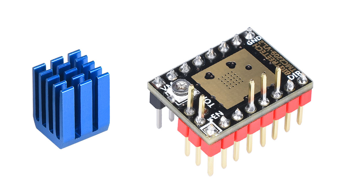
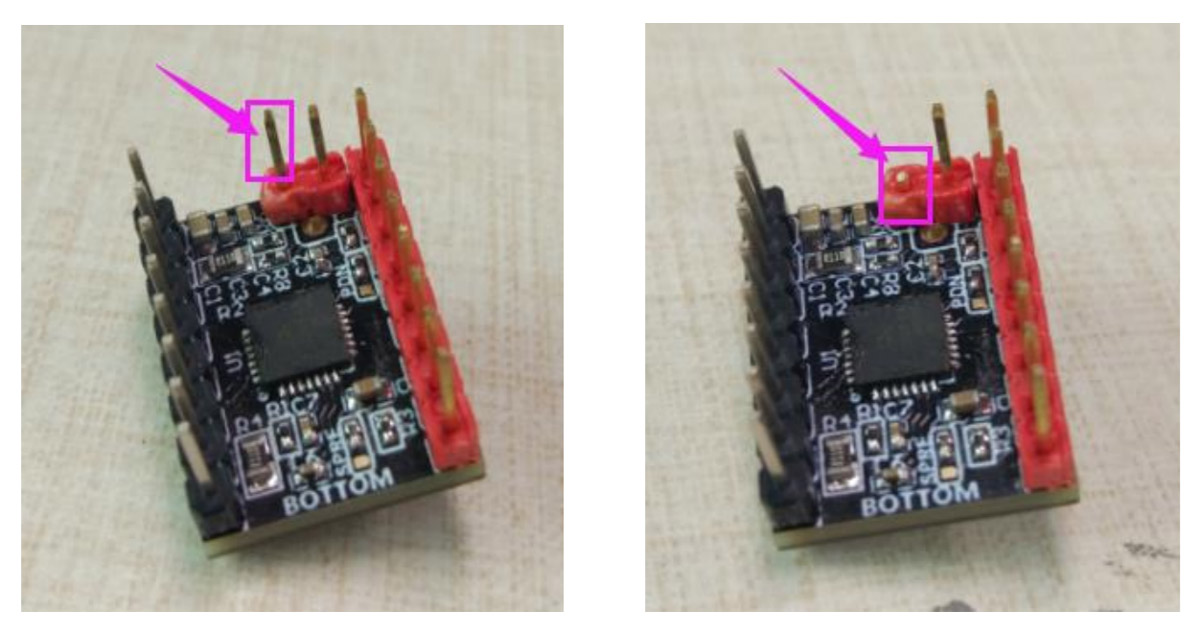
BigTreeTech, the company behind SKR electronics, also develops its own drivers that mount the TMC2209 chip. They are very easily distinguished since, as in the previous driver, the name and version are printed on the top of the plate.
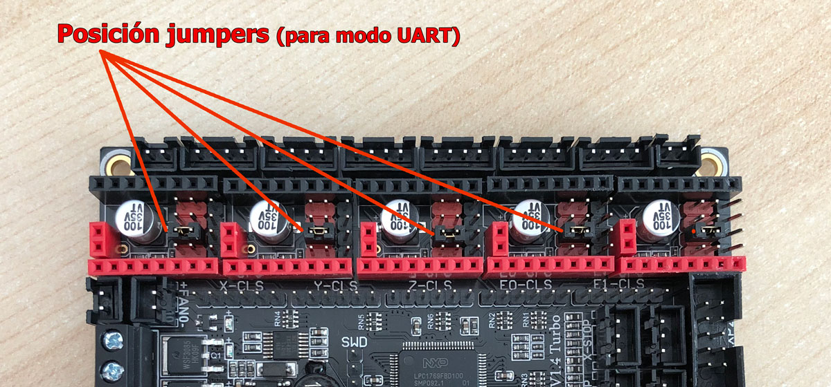
If this is your case, configuring them for UART mode could not be easier. First of all, extract all the jumpers from your board and leave only those in the MS3 position in place, as you can see in the image below (click to enlarge).
With this simple modification should be enough to have a smart UART and StallGuard™ mode, and we will be able to use X and Y motors without limit switches.
According to the manufacturer’s documentation, if you only want the smart UART mode and you will continue to use mechanical limit switches for the X and Y motors, they recommend cutting a driver pin as you can see in the image below.
Since cutting to me personally seems like a bit of a drastic measure, you can choose to carefully fold it or blend to one side. This way if in the future you want to change the configuration and use them in Sensorless mode (without mechanical limit switches), you can do it without any problem.
Drivers TMC2209 FYSETC V3.0
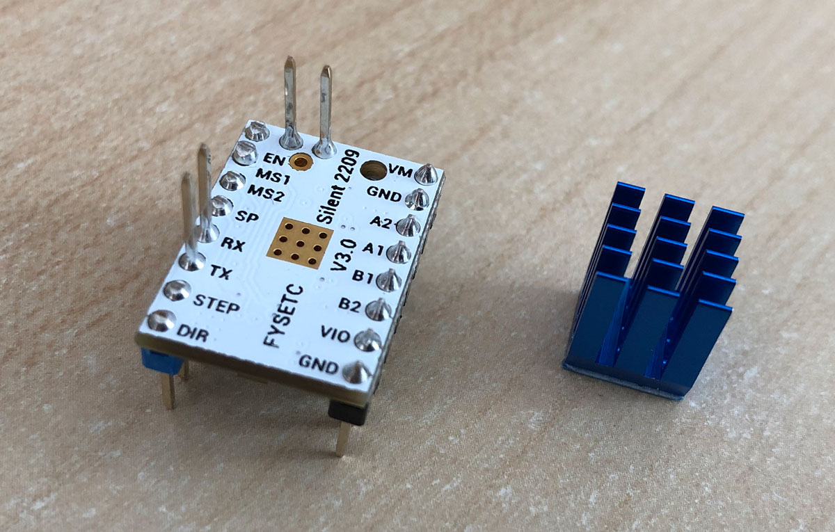
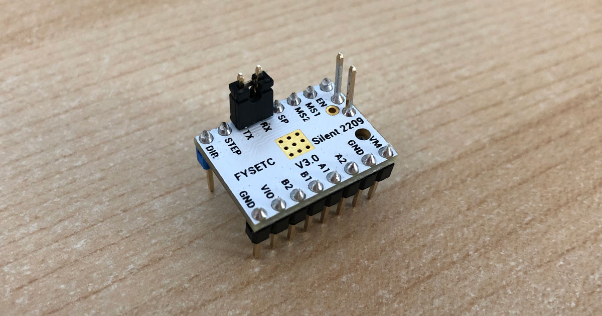
The company FYSETC, famous for selling its own electronics, develops drivers with the TMC2209 chip that you can see in the image above, and which are the ones that I have installed on my 3D printer.
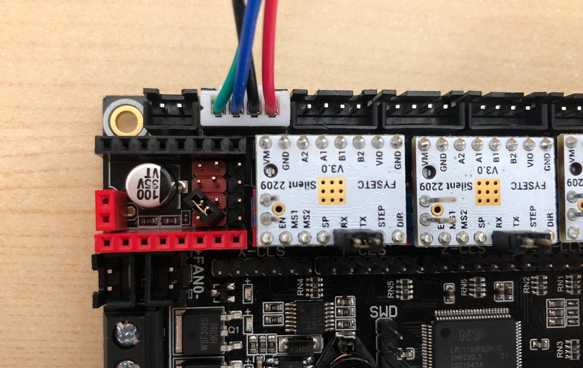
To put them in smart UART mode and use the StallGuard™ function (without limit switches), you only have to use two simple jumpers that I am going to show you in the following images.
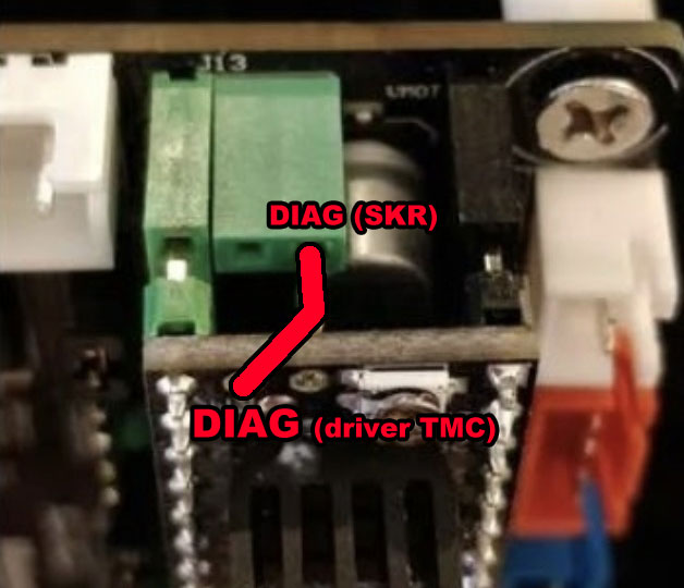
First of all we are going to put a jumper in our SKR electronics in an unorthodox way with a diagonal jumper . It may seem strange, but in this way we will avoid adding unnecessary cables. Of course, try to do it with great care so as not to excessively damage the pins.
In the image above you can see how I did it. I have only removed the driver on the X motor so that it is exposed and you see exactly which pins are the ones that must be jumpered diagonally. Obviously you will have to do it in all those that you want to activate UART and StallGuard™ (Sensorless).
Then, and to finish, you must put another jumper directly on all the drivers. Specifically you need to bridge the RX and TX pins , as you can see in the image below (click to enlarge). And with this, we would already have everything configured.
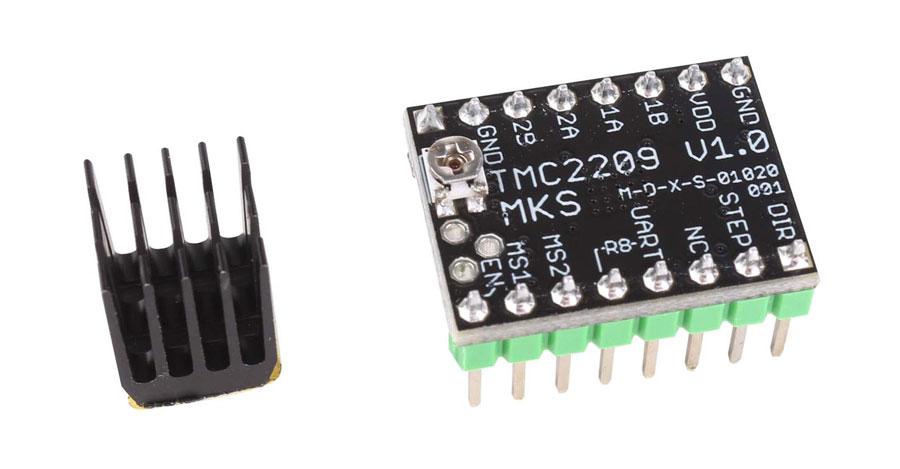
Drivers TMC2209 MKS V1.0
The manufacturer of electronics and other 3D printing components Makerbase, also offers us in-house drivers. As usual, in our SKR electronics we will only have to jumper the MS3 line with a jumper in each of the motors that we want to activate UART and Sensorless.
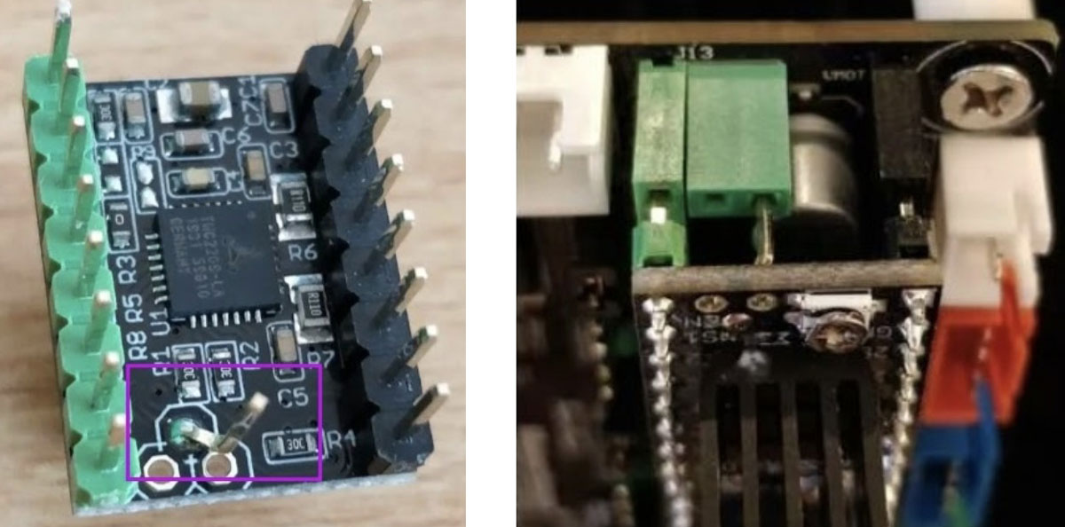
Then in the drivers you will have to bend “by hand” the DIAG pin to match the DIAG connector on the SKR board . I leave you image below so you can see how it was in a user who made this modification.
After put the drivers in our electronics, and verifying that it connects the DIAG lines of driver and board completely well, we will have UART + Sensorless available.
Drivers TMC2209 MKS V2.0
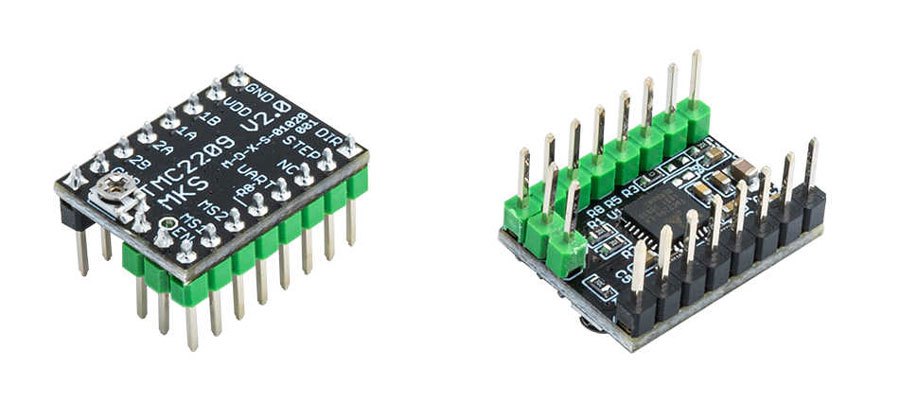
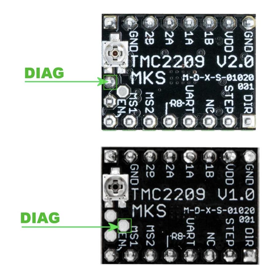
After the version of drivers TMC2209 MKS v1.0 it seems that Makerbase changed the position of the DIAG pin in its drivers v2.0. This important improvement results in not having to make any kind of modification to our TMC2209 MKS v2.0 drivers.
As you can see in the following image (click to enlarge), they changed the position of the DIAG of the vertex of the triangle to another position, which turns out to be the same as that of DIAG1 of our SKRs, a great success for users of these electronics.
So officially we can affirm that this is the driver that offers the easiest to mount on our SKR v1.4 electronics.
However, as always, we must activate the UART + Sensorless mode on our board, so we will follow the usual instructions, I leave the image below of the position of the jumpers.
Drivers TMC2209 WATTEROTT V2.0
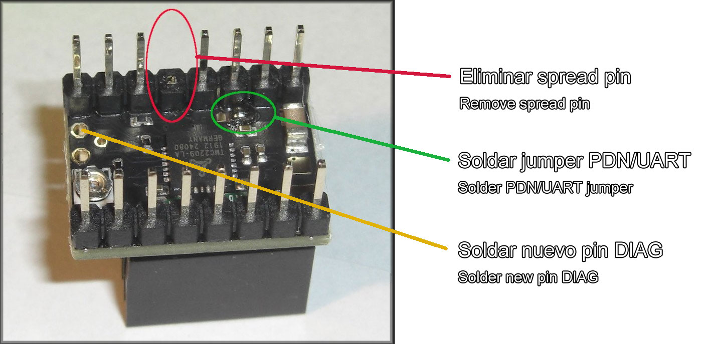
Watterott is another manufacturer of TMC drivers, although in this case the modification may be a little more laborious, since we will need to carry out 5 operations (2 in our SKR v1.4 electronics and 3 in the driver) and a kind of “invention” that I will explain later.
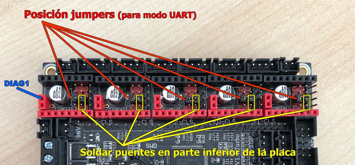
In the image above you can see the modifications that must be made on the electronic board. A jumper that we will place in the MS3 position (indicated by the red lines) and then a jumper by soldering on the back of our electronics. We must do this with our soldering iron, tin and a little bit of skill (in the image in yellow).
After having finished both modifications on the SKR v1.4 / v1.4 Turbo board, we will proceed to make the appropriate modifications to our drivers. In the image above you can see the 3 operations to perform (click to enlarge). In short, delete/cut a pin, solder an “extra” pin to our driver and finally a jumper in PDN/UART, as you can see.
Ok, we have the SKR board and the driver ready, now the last thing we should do is the following. The pin that you have soldered in the driver is the one that corresponds to the DIAG data line. In an ideal world, when we already click the driver on the board it should match, but in our electronics the DIAG pin does not match in the position that you soldered the pin on the driver.
 If you look at the first image that I put, I indicate in blue which is the DIAG1 pin in the SKR and it is in the third position (starting from the bottom). However, in the driver it is in the second position, so when you click it it will not be in the correct position.
So you are going to have to put a fairly long pin and make a couple of doubles, so that when you click it it fits into the hole next to it (and not the one that corresponds to it). I leave you here an image so that I can get you out of doubt (click to enlarge).
And well, with all this you should already have your TMC2209 Watterott drivers operating in UART mode and without any type of limit switch (Sensorless).
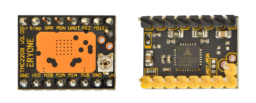
Drivers TMC2209 ERYONE V3.0
Finally, in this list of TMC2209 Drivers from the different manufacturers I know, we would find the driver belonging to the Eryone company. In principle I was not going to add it, since I do not have enough information about it except for a user who did seem to work UART mode without problem.
The first thing we should do is configure our SKR v1.4 electronics as we have been doing, placing a jumper on MS3.
Then as usual, you must connect the DIAG pin of the driver to DIAG1 of your SKR electronic board. Unfortunately in this case the pin does not match either, so you will have to deviate the pin again to fit the one on the board.
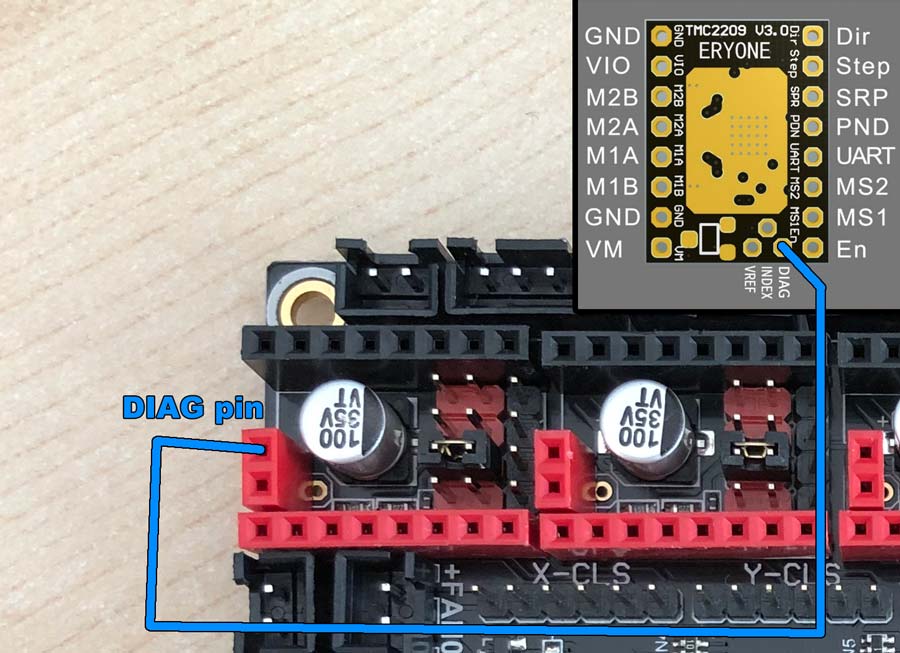 In this image (click to enlarge) you can see where the DIAG is in each of the two components (board and driver), and how to link it.
If you have one of these drivers and manage to locate DIAG and activate UART + Sensorless, do not hesitate to let me know, since I have no confirmation that it will be operational.
Verifying UART communication

After having made every one of the necessary modifications, you must test whether UART is already working correctly. It is easy to make a mistake on a pin, especially if you have to do many modifications.
Also think that you have to do it in at least 3 or 4 motors, the odds as you can imagine of having made a mistake soar. So let’s check if the whole process went well.
There is a very simple way to determine if we already have UART smart communication. If you remember correctly, while configuring our Marlin firmware, we activate an option called MONITOR_DRIVER_STATUS.
This option offers us the possibility of using a series of very interesting GCodes to monitor the TMC2209 drivers. They are as follows:
- M906 – Set or get motor current in milliamps using axis codes X, Y, Z, E
- M911 – Report stepper driver overtemperature pre-warn condition
- M912 – Clear stepper driver overtemperature pre-warn condition flag
- M122 – Report driver parameters (Requires TMC_DEBUG)
The command that we are going to use will be the M122, in this way a series of parameters and values established in our drivers will be sent to us on the screen, and thus we will verify that they are communicating via UART with our electronics correctly.
To send the M122 command I usually use Repetier. Not that it is better or worse than Pronterface (another alternative), but I used it for many years as a Slicer and I use it when I need to send some g-code command. You can also use the g-code emulator offered by the TFT35 hybrid display, but it shows so much information that it is not recommended.
In this image you can see the output of the M122 command on the Repetier log screen. It shows you a multitude of parameters and their assigned values, such as the configured voltage, the established micro steps, the StallGuard configuration and its Marlin values and many other interesting things.
All this would not be available if we had not established UART as a communication mode and connected the DIAG pin a of the driver to our SKR board.
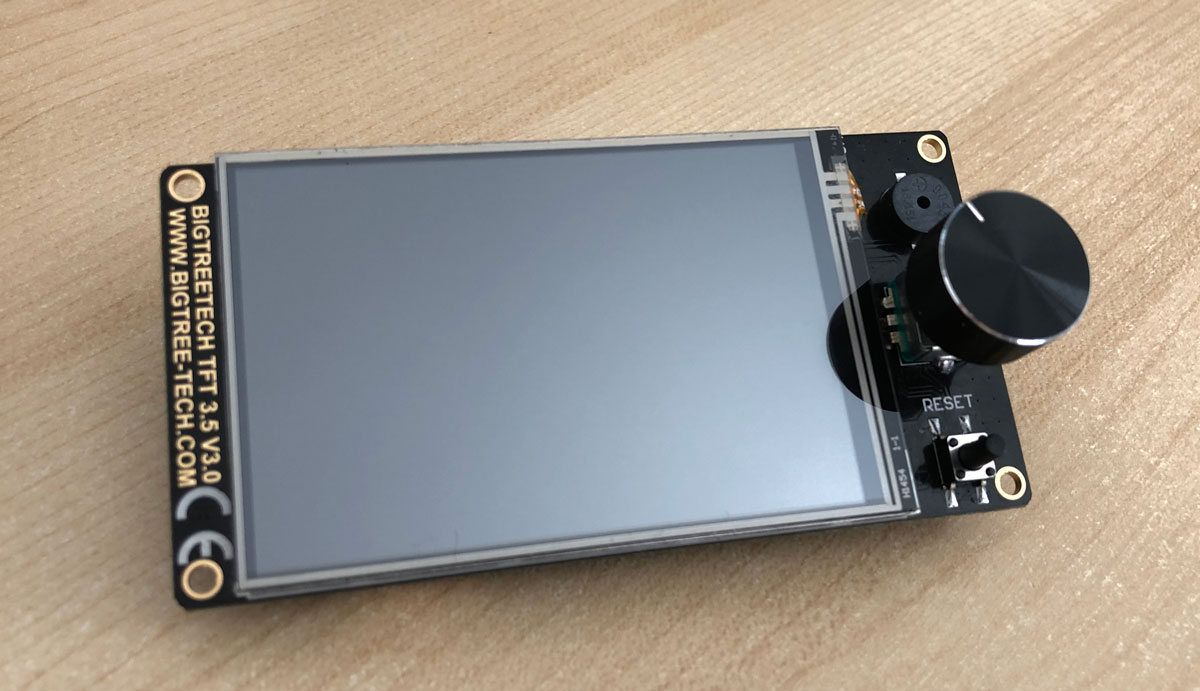
Display TFT35 Bigtreetech V3.0 “Hibrid”
I have to confess that the “hybrid” BIGTHREETECH screens are truly spectacular. I have always preferred the Marlin menus on my MINI12864 Displays and have the possibility to activate / deactivate any firmware option without waiting for odious display updates that either arrive late or simply do not arrive. This is something that usually happens on TouchScreen displays.
I remember some time ago trying to activate the BabyStepping function with G-Code commands on TouchScreen displays and not being able to. And although it is hard to believe, that function exists since version 1.x.x of Marlin!. Something vital to calibrate the prints on the first layer correctly.
When I first read that these displays emulated both modes, I was pleasantly impressed, so I decided to purchase one for myself SKR electronics without hesitation. What don’t you want to complicate yourself and you’re only going to print? You choose TouchScreen mode. What do you want all the power and versatility of Marlin? You switch to the Marlin emulator, it’s that simple.
And this does not mean in any way that the TouchScreen mode is not complete, vice versa. It has almost all the functions that Marlin offers and that you need to use every day. The support from the programmers is noteworthy.
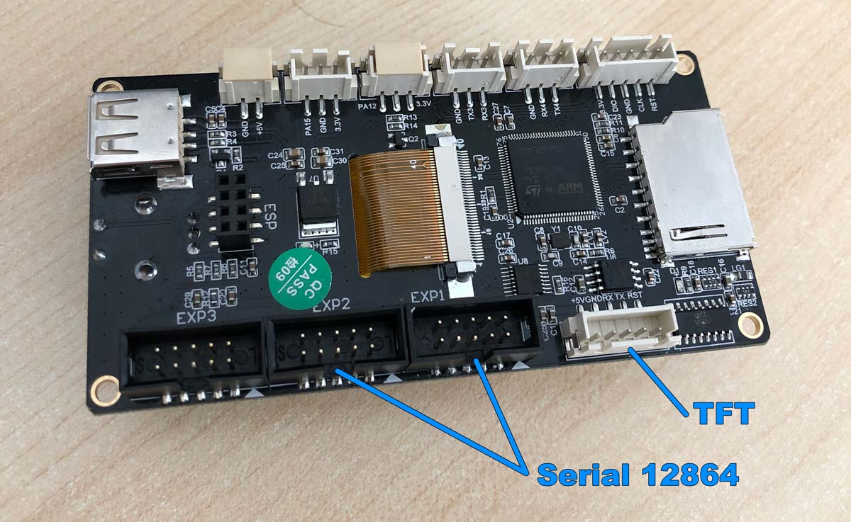
Because we are going to use both modes, we will need to make 3 connections on our display board, which are the ones you can see in the image above (click to enlarge). The 2 typical serial 12864 connections, which are the EXP1 and EXP2 connectors. And then the TouchScreen connector that SKR will use to communicate with the display, marked as TFT in the image.
In the video below you can see how to switch between MARLIN modes (text mode) to TOUCHSCREEN mode (touch screen). As you can see, simply press the main button for 4 seconds and it will give us the option to change to the desired mode.
You will excuse me for the quality of the video, since I do not have the support yet designed and I had to hold it with my own hands, but I think the process is perfectly visible. And by the way, if you see it in its entirety you will be able to discover how to use the G-Codes emulator that comes with the TouchScreen mode.
I have precisely executed the M122 command and so you see on the screen how it is verified that the printer has the TMC2209 drivers configured in UART smart mode.
Some final recommendations
It is likely that after compiling the Marlin firmware and uploading it to your electronics, an Eeprom error may appear on your Touchscreen or the Marlin emulation screen. If this is the case, don’t worry as it is normal.
You must run these g-code commands one by one (don’t insert them at once) and the problem will be solved. The commands are M502, M500 and M501 in this same order. I leave you here the description of what each of them does.
- M502 – Full reset to factory settings. It does not require the EEPROM_SETTINGS parameter.
- M500 – Save all the current configuration to our EEPROM.
- M501 – Loads the current values from the EEPROM.
Another problem that usually appears when we use the Touchscreen mode is that it indicates that there is no communication with our printer. That is because we have different communication speeds selected in our Marlin Firmware and on our display.
If you have followed this manual to the letter you will remember that we set the communication to 250,000 baud in Marlin (#define BAUDRATE 250000). Now you must locate on the display where the communication is configured and indicate this same value.
Remember that you have to do this from the “Touch mode”, not from the Marlin emulation (text mode). To make your task easier, I put the route to follow:
MENU -> CONFIGURE -> UART SPEED
And well, for now this is it, I hope this article has helped you. It has been a little more laborious than I expected, but I think it is very worth being able to have all this information in a single article for future references from our entire community (in which I include you).
If you have any doubts or queries, or find an errata in it, something that I do not rule out due to its length, join our community on any of the social networks.
I also want to thank our partner Juanjo from Telegram channel de 3DWork his invaluable collaboration in its development, since he has given me his unconditional help from the first minute.
If you wish, you can find other interesting articles in 3DWork at the following links:
- DyzeXtruder Pro: Analysis of a high-performance extruder for professional environments
- MKS TFT35 Display: Latest updates v106 and v107 available
- The Spaghetti Detective: Monitoring Octoprint from the Internet safely
- Powering the Raspberry Pi from the power supply of your 3D printer
- Booting our Raspberry Pi from USB with an SSD hard drive (or pendrive)
- Maker Ultimate 2: Review of the latest Monoprice printer
- Analyzing the new resin printer Phrozen Sonic Mini (Review)
- MKS Robin Nano v1.2: Analyzing the new MakerBase 32bit boards
- Hollow 3D objects with ChiTuBox to save resin
- 10 reasons to use ChiTuBox with your resin printer (SLA/DLP)












Great work, thank you!
Thanks for your comment Mitja,
Regards!
Can this SKR 1.4 Turbo board also used for a cnc mill?
I am not expert on CNC, I apologize Jones. By the way, perhaps will be better try to use a more specific electronic board, drivers and motors for build one CNC Mill. If someone can give you some recommendations about it that have experience with this will be great.
Regards!
I’m using it with a simple DIY CNC router, if that helps at all. I’m using the Marlin firmware, and it’s a few extra steps to translate the gcode for it, but it’s working well
Thanks for share your experiences 🙂
Hi, yes, off course, and the skr 1.4 turbo is quite interesting as there’s external connections to drivers already present onboard ( “x,y,x…-cls” for closed loop drivers).
Anyway adapters are also present to insert in lieux of drivers, to be able to use powerful cnc drivers, with a better power management then, allowing to use different voltages (ie. 45V – 50V) from the board itself (max 24V…)
And as well Marlin support LASER and cnc MILL applications.
A lot of fun possible with this board !
I have the SKR 1.3 and the Eryone steppers and through trial and error figured out what you listed here (would have been nice if I found this first). For me on the SKR 1.3 I could put a flying wire from the top of the driver to the correct post on the bank of diag jumpers which seemed the easiest solution. The alternative I guess would be to clip the bottom pin, put a through pin in the next hole and jumper them together on the top of the driver.
In ANY case – they worked once I did this. So yes they can do stallguard if you connect that pin to the right place.
Thanks a lot for share your thoughts with us, and nice to hear that you finally solved it.
Regards!
awesome, just one thing with the watterott 2209 V2, at lesat with my version:
you showe the center pad connected to the right one (oriented like in your picture) but I could only get the drivers’ connection with M211 after soldering center with left or all three pads.
…again: f****ing awesome guide
Thanks a lot for your information Chistopher,
Regards!
Mate, thank you so much. i spent days trying to figure out the UART connection issues on my SKR1.4 turbo / watterott TMC2209 combo. I can confirm that soldering the left and middle pads fixed it. The middle and right solder connection works on the skr 1.3 but not the 1.4.
Hi,
Would you maybe know how to hardware connect TMC2209 FYSETC V3.0 and MKS SGEN L?
╔══╦╗──────╔╗
╚╗╔╣╚╦═╗╔═╦╣╠╗
─║║║║║╬╚╣║║║═╣
─╚╝╚╩╩══╩╩═╩╩╝
╔═╦╗ °☆°☆°☆°☆°☆°☆°
╚╗║╠═╦╦╗ ☆°
╔╩╗║╬║║║ ☆°
╚══╩═╩═╝ ☆°
For your hard work
It’s Greatly Appreciated
Thanks for visit our blog! 🙂
hi i have a problem with BBT 1.4 turbo and tft35 v3.0. I can’t get it to recognize the printer in touch mode. I have changed the baudrates and ports but the message no printer not connected continues.
Buenas, increible trabajo, quisiera, de ser posible, me puedan ayudar, e comprado una SKR 1.4, se la voy a colocar a mi impresora, y no tengo muy en claro lo del sensor de filamento, actualmente, lo tengo colocado en una Ramps, pero no logro hacerlo funcionar, en la SKR 1.4, desde ya agradecería su ayuda.
And what about SKR1.4 TURBO with TMC2208 v3. 0, I’ve four wires in the confection where should I connect them, there are no pin on the board tmc, Just a hole. Thanks for helping
It seems you have the most complete tutorial so far on the SKR 1.4 + TMC2209s. I bought a kit from BigTreeTech and the one thing that is stopping me at the moment is setting the current values for the drivers. Each place I’ve looked has a slightly different suggested method and at this point I am confused. I am setting up my drivers as UART without sensorless homing. Should I set the micro stepping value or leave it automatic? Should I set the current values or just ensure the Rsense resistor value is correct?
First of all thanks for your words, I appreciate.
In my printers I leave microstepping as it comes from Marlin, and drivers I use 850, 850, 850 and 600 (X, Y, Z and E0).
For me works nice with this values. Regards!
Hello! Thank you for the research! I have currently purchased the board and drivers, but did not purchase the display. Is it mandatory that you purchase the display as well? I guess I really didn’t realize it was needed.
Hi Devin,
It is not necessary to get hold of the TFT35 display that appears in the article. As these boards have EXT1 and EXT2 connectors as usual, you can use it for other displays without problem.
By the way, I recommend this BTT screen, because the hibryd mode is impressive and can be changed in real time.
Thanks for read the article and for your comments.
Regards!
Brilliant guide. With the Eryone 2209 you can have sensorless homing without the need to bend or modify the pins.
The drivers come with Jumper cables, If you use a cable from the top pin for the Diag and connect it to the Signal pin for the end stop it works.
Thanks a lot for your words, and of course for your information, for sure other users will take advantage of them 🙂
Best regards!
Te hago una consulta, vi que hay varios modelos de driver tcm2209 V3.0, compre uno que tiene las siguientes impresiones DIR/STEP/CLK/RX/TX/MS2/MS1/EN
no sabria como ponerlo en UART, vi que otros 2209 se coloca un jumper en TX/RX pero casualmente el mio no es igual a ese driver.
el otro driver 2209 3.0 al que me refiero esta asi
DIR/STEP(/TX/RX “QUE AHI VA UN JUMPER”)/SP/MS2/MS1/EN
PIDO AYUDA 🙁
Hi, first of all: great guide. First one I found and it works without further research for missing settings. Just awsome 😉
But I wonder why you set the microsteps to 16 even tho the TMC 2209 support up to 256 microsteps. Is it that 16*16 is 256 (any calculation by Marlin) or is that just accidentally? Whats the reason you set it to 16?
I have the 2209 V2 drivers from MKS but I cant get them to work on my SKR 1.4 Turbo. I placed the Jumpers like you said. Do I change something on the drivers themself? Maybe change the solderpads?
I have done all the steps above and my z axis on my ender 3 pro starts it’s first line it gets to the back and keeps going doesn’t stop. Then goes to lay it’s second line get to the front and does the same thing before starting it print. What can I do to fix this.
Thanks for this. I have a silly question but I’ll ask it anyway (because someone else may have the same question). The SKR board has space for 5 stepper motor drivers, but output for steppers, can the z-axis steer motor driver be configured to signal the Z1 and Z2 axis together? In simpler terms, can I run the board with only 4 stepper motors and still do dual-Z motors, X-Motor, Y-Motor, and the Extruder?
You can.
The SKR board has indeed 5 stepper drivers locations. If you look closely at the back of the board, near where the Z stepper is, you’ll see two connectors labelled “ZA” and “ZB”. These are made to run 2 motors through 1 stepper driver on Z axis.
You won’t be able to set each motor separately, though.
It *might* be a better idea to run each Z motor with a dedicated stepper driver (using E1 here), since it makes it possible to auto-align Z using a single G34 G-Code command.
PIDO AYUDAAAAA 🙁 TENGO DRIVER TCM2209 V3.0 PERO NO SE COMO CONECTAR MODO UART, EL TUTORIAL SUPER BUENO PERO MI DRIVER TIENE IMPRESO DIFERENTE.
DIR
STEP
CLK
RX
TX
MS2
MS1
EN
Y EL TCM DEL TUTORIAL LO TIENE ASI
DIR
STEP
TX (VA EL JUMPER)
RX (VA EL JUMPER)
SP
MS2
MS1
EN
NOSE COMO HACER CON EL JUMPER EN MI DRIVER 🙁 ALGUN GENIO ME SABRIA GUIAR
Hi, now I found the time to upgrade my KLP with the BTT SKR 1.4turbo, TMC2209 and TFT v50. My problem is, that I can’t calibrate. When I do it onboard in the menu, when I hit “leveling”, it homes and then crashes the bed. When I hit “ABL”, it homes and then moves down 20mm and stops. No more movement and no more function (busy: paused for user), I have to turn off and on. Also with Pronterface:
SENDING:G33 P4
G33 Auto Calibrate
Checking… AC
.Height:300.00 Ex:+0.00 Ey:+0.00 Ez:+0.00 Radius:135.40
. Tx:+0.00 Ty:+0.00 Tz:+0.00
echo:busy: processing
echo:busy: processing
echo:busy: processing
echo:busy: processing
Deploy Z-Probe
echo:busy: paused for user
and then only echo:busy: paused for user
Also when I try to heat up, after a few minutes of heating it fails and run into an error.
Any hints for me, please?
Great thanks.. only I would say you need to produce the same but include the Klipper version rather than marlin.. it seems the world is shifting towards Klipper for features and ease of setup / updates.
Hi, congratulations for this article, you can get the guide on how to install “TWOTREES TMC2209 v2.0” sensorless mode? Thanks!!
I have bltouch on my printer and when I enable Power Loss Recovery, as soon as it switches to printing, I get this error: reset the printer and start printing.
skr 1.4 turbo
tmc 2209
bigtreetech tft 3.5- v3
When Power Loss Recovery is turned off, it smoothly bed-levels and switches to printing. please do not give up your support
Marlin-bugfix-2.0.x.zip
When I make the settings like this, it works, but it starts printing from the beginning.
#define POWER_LOSS_RECOVERY
#if ENABLED(POWER_LOSS_RECOVERY)
#define PLR_ENABLED_DEFAULT false // Power Loss Recovery enabled by default. (Set with ‘M413 Sn’ & M500)
//#define BACKUP_POWER_SUPPLY // Backup power / UPS to move the steppers on power loss
//#define POWER_LOSS_ZRAISE 2 // (mm) Z axis raise on resume (on power loss with UPS)
#define POWER_LOSS_PIN -1 // Pin to detect power loss. Set to -1 to disable default pin on boards without module.
//#define POWER_LOSS_STATE HIGH // State of pin indicating power loss
//#define POWER_LOSS_PULLUP // Set pullup / pulldown as appropriate for your sensor
//#define POWER_LOSS_PULLDOWN
//#define POWER_LOSS_PURGE_LEN 20 // (mm) Length of filament to purge on resume
//#define POWER_LOSS_RETRACT_LEN 10 // (mm) Length of filament to retract on fail. Requires backup power.
https://drive.google.com/file/d/17of3NCNayajw4Hj3cXoDSV8FRk_MpxzK/view?usp=sharing
I have bltouch on my printer and when I enable Power Loss Recovery, as soon as it switches to printing, I get this error: reset the printer and start printing.
skr 1.4 turbo
tmc 2209
bigtreetech tft 3.5- v3
When Power Loss Recovery is turned off, it smoothly bed-levels and switches to printing. please do not give up your support
When I make the settings like this, it works, but it starts printing from the beginning.
#define POWER_LOSS_RECOVERY
#if ENABLED(POWER_LOSS_RECOVERY)
#define PLR_ENABLED_DEFAULT false // Power Loss Recovery enabled by default. (Set with ‘M413 Sn’ & M500)
//#define BACKUP_POWER_SUPPLY // Backup power / UPS to move the steppers on power loss
//#define POWER_LOSS_ZRAISE 2 // (mm) Z axis raise on resume (on power loss with UPS)
#define POWER_LOSS_PIN -1 // Pin to detect power loss. Set to -1 to disable default pin on boards without module.
//#define POWER_LOSS_STATE HIGH // State of pin indicating power loss
//#define POWER_LOSS_PULLUP // Set pullup / pulldown as appropriate for your sensor
//#define POWER_LOSS_PULLDOWN
//#define POWER_LOSS_PURGE_LEN 20 // (mm) Length of filament to purge on resume
//#define POWER_LOSS_RETRACT_LEN 10 // (mm) Length of filament to retract on fail. Requires backup power.