One of the great applications of Raspberry Pi devices, of which I have been an unconditional fan for many years, is that of being able to monitor our 3D printers remotely over the Internet.
This offers us the possibility to review our printed parts at all times, see if there has been a serious error during the process or simply review the remaining printing time.
To do this you must install an Open-Source application that many of you may already know called OctoPrint. And if you still do not know it and you are interested, I highly recommend that you read an article I wrote some time ago: Octoprint: Manage your 3D printer remotely with Raspberry Pi and Octopi
If you do it and install the Raspberry Pi, or if you have already configured it for this function for some time, you will know the real nuisance that it is to have another charger around the table of your printers. I have 3 printers and I have plenty of cables everywhere, without counting the lack of plugs or additional power strips on the floors.
Well, a possible very practical solution is to feed the Raspberry Pi directly from your 3D printer, how do you hear it. However, it is very strange that you can get 5v. of it, so we will need to make an extremely simple small modification to it. Let’s go there…
Hardware needed
Here I leave some of the components that appear in the article. They are affiliate links to different marketplaces, so if you use them we will have a small commission and you will be helping to support the 3DWork.io project.
| Raspberry Pi 4 | ||||
| MicroSD Card + Reader | ||||
| Voltage regulator (LM2596) | ||||
| Tin soldering iron |
STEP 1: Looking for a power line
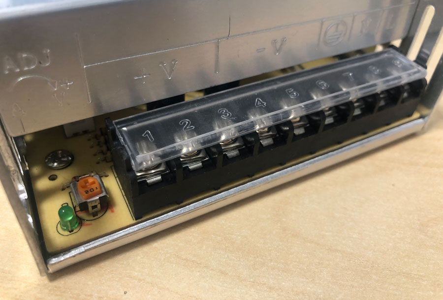
The first thing we are going to do is determine from where we are going to get two lines to power our Raspberry Pi , and what better place than our available power supply. The most normal thing at this point is that you have a 12V or 24V power supply, which is what the different manufacturers usually mount.
So you must locate your power supply and check if you have 2 free lines (positive and ground), to be able to use them for that purpose. It may be that your power supply is in good access (I congratulate you), but also that you have it encapsulated in some closed chassis or similar, in that case you must locate it and take 2 cables from it to the outside, it will not be too difficult for you.
Our Raspberry Pi requires a 5V supply , so as you can imagine we must convert the output of our source to a stable 5V voltage, enough so that it can operate without any problem. For this, we will need a converter that will reduce the voltage, and in this way remove the power supply of our Raspberry Pi through.
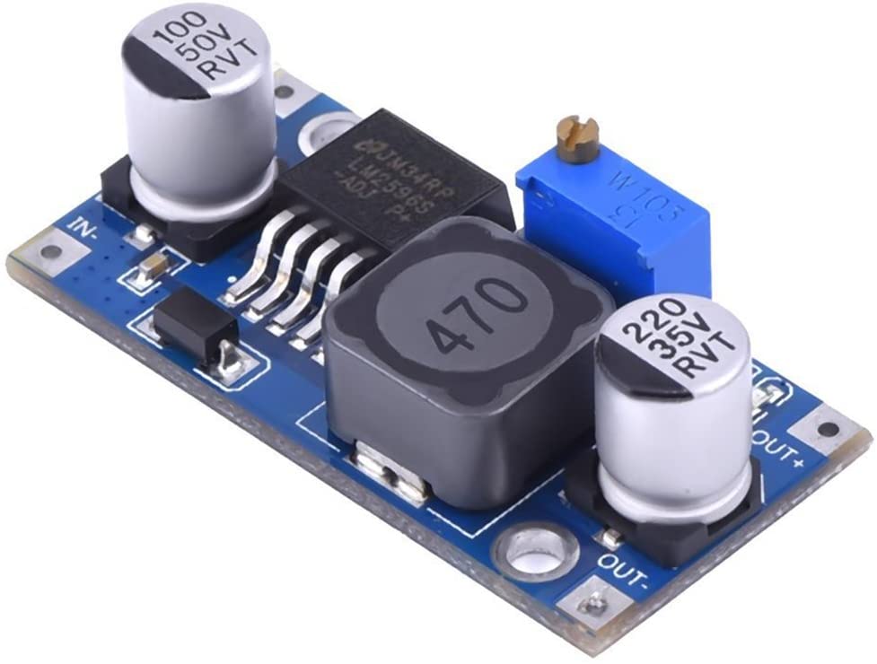 These converters are quite common components, and you can find them in the different Marketplaces existing in the network.
In fact, they are also widely used to reduce voltages from 24V to 12V and install silent fans in our printers . Trying to locate, for example, a 24V Noctua fan is an impossible task, so this alternative is quite interesting and inexpensive.
STEP 2: Wiring our converter
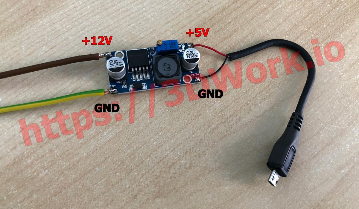
If you look closely at the converter module, you will see that in each corner there are two areas where you must solder the necessary cables. On the left, where IN + and IN- (input) appear, we are going to wire directly from our power supply, always respecting the polarity (positive with positive and vice versa).
At the other end we will see OUT + and OUT- (output), and this is where we must solder the microUSB cable (in Raspberry 1/2/3) or USB-C cable (in Raspberry 4) that we will then connect to our Raspberry Pi to constantly feed it. For this purpose, the ideal is that you locate some spare cable that you have at home, cut it and remove the power lines from it. Normally the polarity should be reflected in the color of the wires (positive red and negative black).
At this point, 2 important recommendations. The first is that you try not to use the original power cable of your Raspberry Pi itself. Chances are that you will use it again sometime certainly, so if you have an old cable or you can buy a cheap one online better. This way you will avoid modifying it again in the near future if you need it again.
The second recommendation is that before cutting the cables that you are going to solder to the converter, keep in mind where you are going to position your Raspberry Pi in the 3D printer. Calculate approximately the length of the power supply cable to the converter, and then the cable that will go from the converter to the Raspberry Pi. This way afterwards there will be no cables hanging and you will get a cleaner installation.
STEP 3: Adjusting the necessary voltage
As I have mentioned before, the most common thing is that you have a power supply in your 12V or 24V 3D printer. As the Raspberry Pi requires a 5V supply, you must adjust the output of the converter to that voltage, otherwise you could damage it without remedy.
For this purpose, in our converter you can locate a small potentiometer, which will allow us to regulate the voltage output (in the OUTPUT) simply by turning sideways.
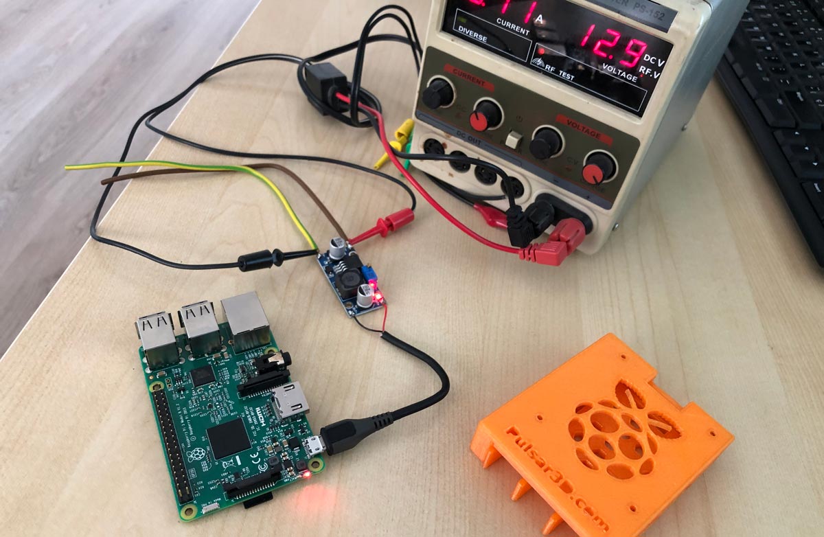
I recommend that you have a multimeter on hand and if possible, a pair of alligator clips. In this way you can click the clamps on the output to the Raspberry Pi and see the voltage in real time while turning the potentiometer. Once you reach 5V leave that value, and you can now connect your Raspberry Pi without any problem.
To configure the correct voltage, I used a power supply that I have at home for my experiments, as you can see in the image above. Almost 13V of voltage comes out of the source, and the Raspberry Pi is receiving exactly 5V after adjusting it with a small screwdriver. So I already left it ready to connect to my printer 🙂
STEP 4: Encapsulation and fixation
Well, we already have our Raspberry Pi running fully powered from our power supply, congratulations!
Once functional, the last step would be to do some encapsulation with our 3D printer. In this way, we will ensure that it does not short circuit anywhere (profile or sheet metal), and it can also help us to fix it later.
Ideally, you would use that splendid 3D printer you have, design one and print it. However, you have plenty of ready-made media ready to print on Thingiverse at this link.
Well, I hope this short article was to your liking. Do not hesitate to add us to our social networks (Facebook, Twitter, Instagram) or visit us on our Telegram channel.
You can find more interesting articles at 3DWork.io at the following links:
- Booting our Raspberry Pi from USB with an SSD hard drive (or pendrive)
- Maker Ultimate 2: Review of the latest Monoprice printer
- Analyzing the new resin printer Phrozen Sonic Mini (Review)
- MKS Robin Nano v1.2: Analyzing the new MakerBase 32bit boards
- Hollow 3D objects with ChiTuBox to save resin
- 10 reasons to use ChiTuBox with your resin printer (SLA / DLP)












Déjanos un comentario