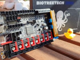
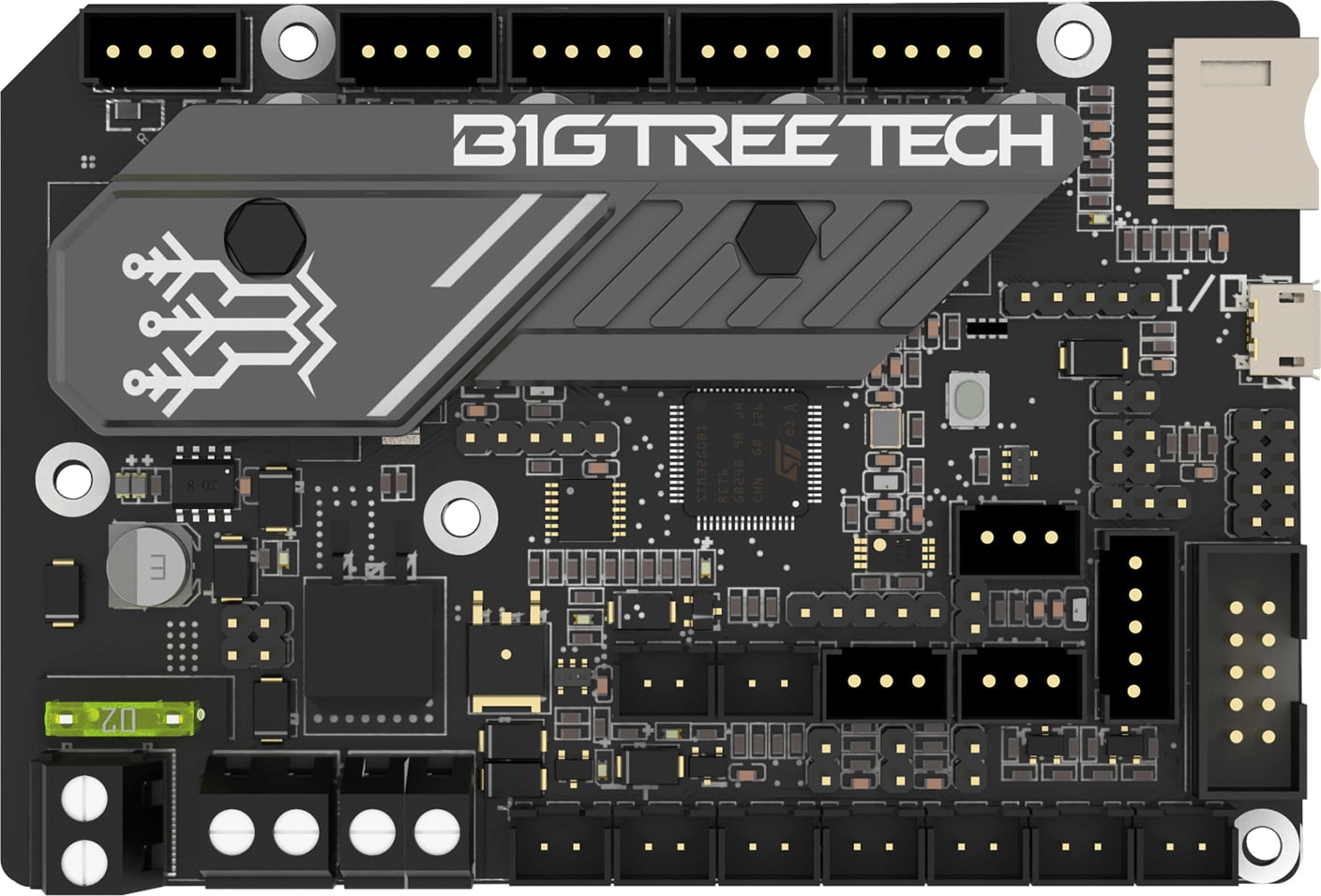
If we already considered it the SKR MINI E3 V2 electronics as one of the best board of its format, the new SKR MINI E3 V3 does not only not disappoint us with the improvements introduced, but it gives it a twist by creating a board with a spectacular aesthetic that will make you want to leave the electronics in view.
And in today’s article we will talk a little about this, their main news compared to previous versions and of course, their configuration with different firmwares.
Introduction
It should be remembered that all the electronic boards of the E3 range are specially designed for the use and/or replacement of the electronics of Creality Ender 3 or Creality Ender 5 printers.
Although they can be used without any problem in other printers according to the wiring and specific characteristics of each one.
If you need more information or help do not hesitate to join the SKR Telegram group @SKR_board_32bits. We remind you that you have more help guides in our Telegram bot @ThreeDWorkHelpBot
Before continuing, we encourage you as always to join our Telegram channel or to follow us on our social networks, where you will find more fanatic people by 3D printing like us.
Where to buy the SKR MINI E3 V3?
You can buy the SKR MINI E3 V3 in different marketplaces and internet shops. By the way, we leave you here some direct links.
If you use them, the price of the product will be the same as if you log in regularly, but 3DWork will have a small commission left. Something that will help us support the project and continue generating content and guides.
As an alternative, you can also use our Markets.sx product search engine for 3D printing, where a single search will show you prices from different marketplaces (Amazon, Aliexpress, Banggood, etc.)
New features in the SKR MINI E3 V3
In this new review of the SKR MINI E3 range we can find a series of improvements with very interesting characteristics as well as at the visual level that will surely create a trend in future electronic boards.
For start, we leave you here an introductory video by Bigtreetech quite interesting:
The most notable improvements include the following:
- New heatsink for drivers and electronics : Which is of a high quality and visually impressive, offering us an excellent finish of the board.

- MCU and EEPROM: ARM Cortex-M0 + STM32G0B1RET6 from 32b to 64 Mhz and 512KB Flash improving previous revisions, in addition to including a 4KB 24C32 on-board EEPROM
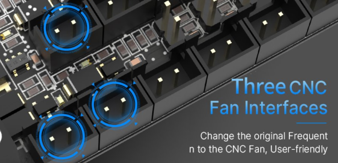
- Fans: Add a third manageable fan for optimal performance
- 3D Firmware : Bigtreetech from its Github added support for both Marlin and Klipper
- Extra protections : New and better protections in thermistors and fan connectors
- Improved connection : Use of Micro USB instead of the old Mini USB
- SPI bus : Option to use 3.3v for SPI output
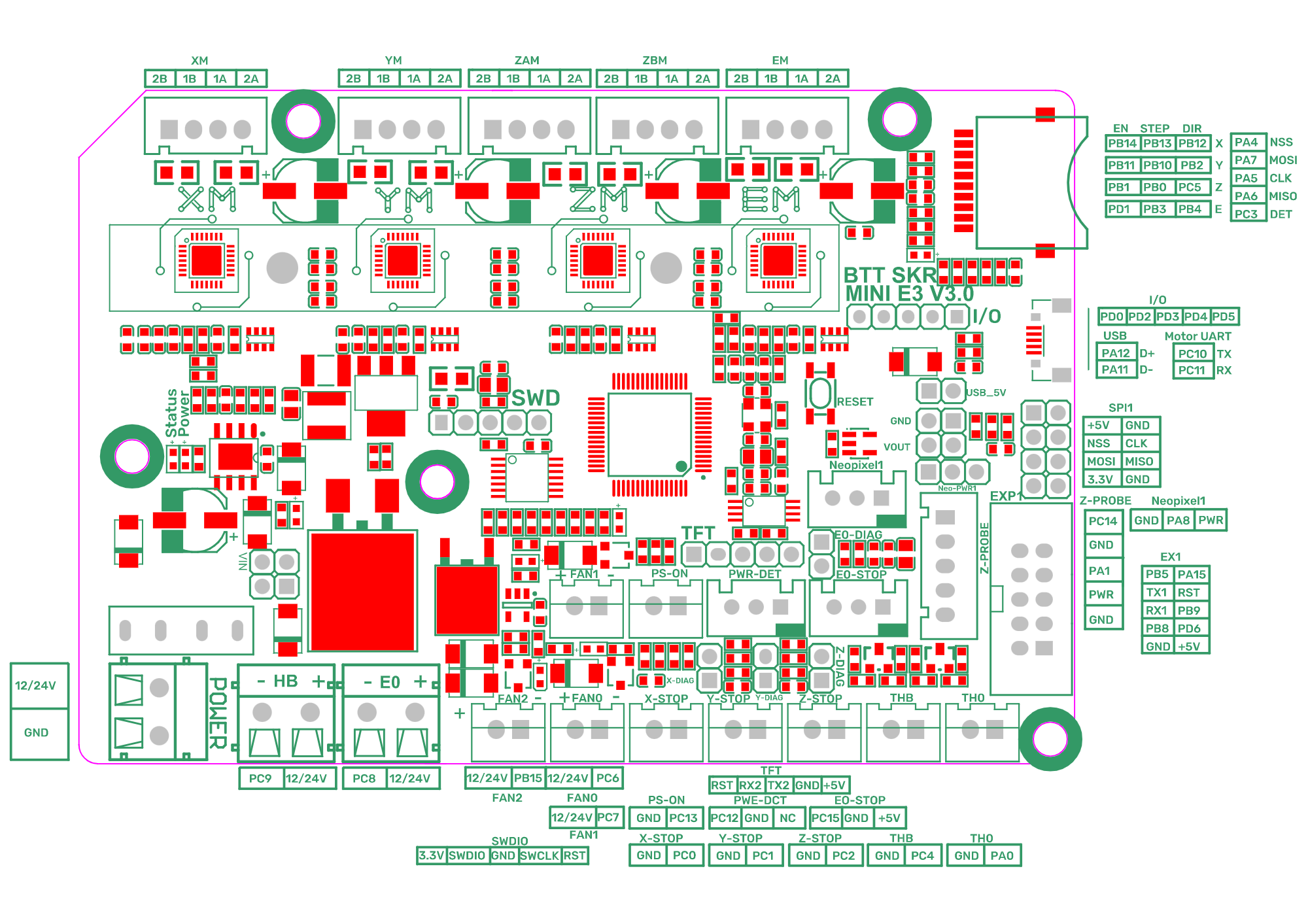
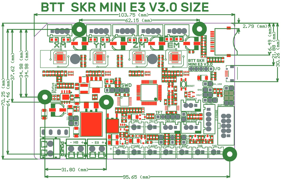
Schematics / Diagrams
We attach the schematics and diagrams of the SKR MINI E3 V3:
Expansion / Improvements
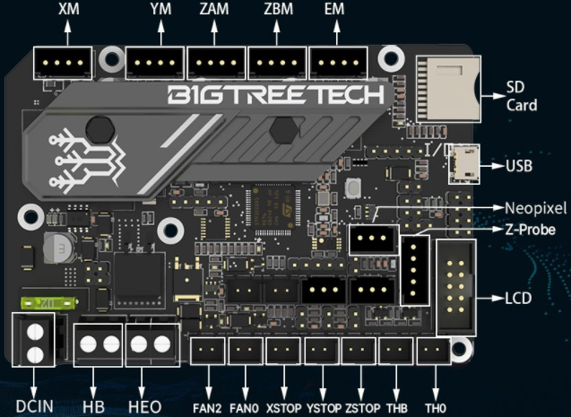
The SKR MINI E3 V3, like the rest of the MINI E3 range electronic boards from Bigtreetech, has multiple dedicated connectors to improve and expand its functionalities by improving our printer with leveling sensors, filament, relay modules, UPS modules, Neopixel or RGB led strips, etc.
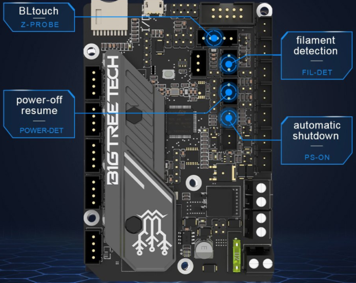
Here are details of some of them:
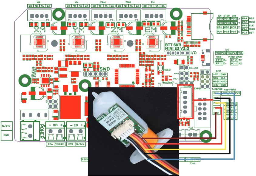
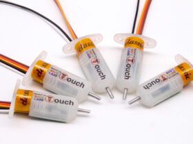
A great improvement for our printers that can make it easier for us to have the first layer as perfect as possible is the installation of a leveling sensor such as the BLTouch for is one of the most versatile.
You have detailed information in our Bltouch guide.
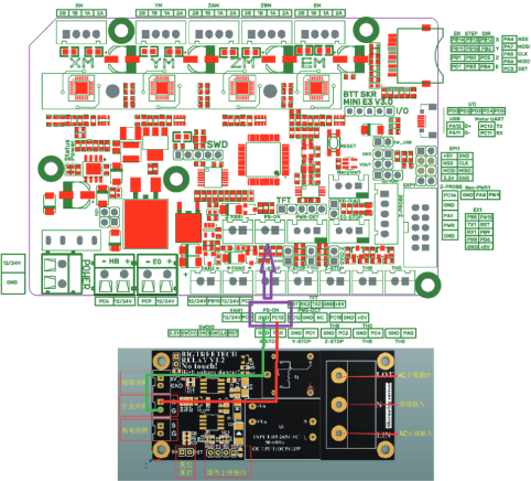
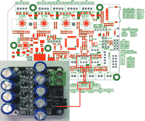
It gives us a control of the on or off of our machine in a controlled way, such as turning it off once the printing is finished.
Like the relay module, the UPS allows us to perform a correct emergency shutdown especially if we use PLR (Power Loss Recovery) / print restoration in the event of any power failure.
You can find more detailed information in the following guide.
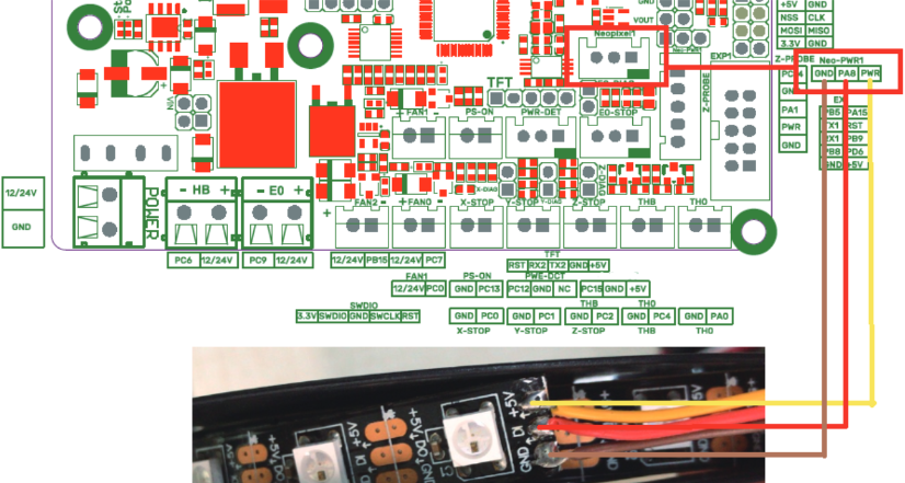
Although it is not a direct improvement in the use of the printer, the inclusion of a controllable led strip is very useful either as lighting of the printing area as well as event management.
We encourage you to review the Neopixel guide where you will find more detailed information.
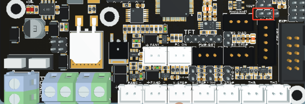
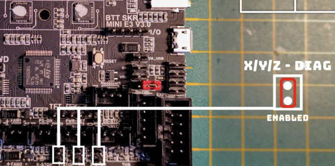
In the case that we use many external components using the board’s 5V bus, and especially in the case of using LED strips, it is advisable to install the Bigtreetech DCDC 5V.
For its use / configuration we have a jumper:
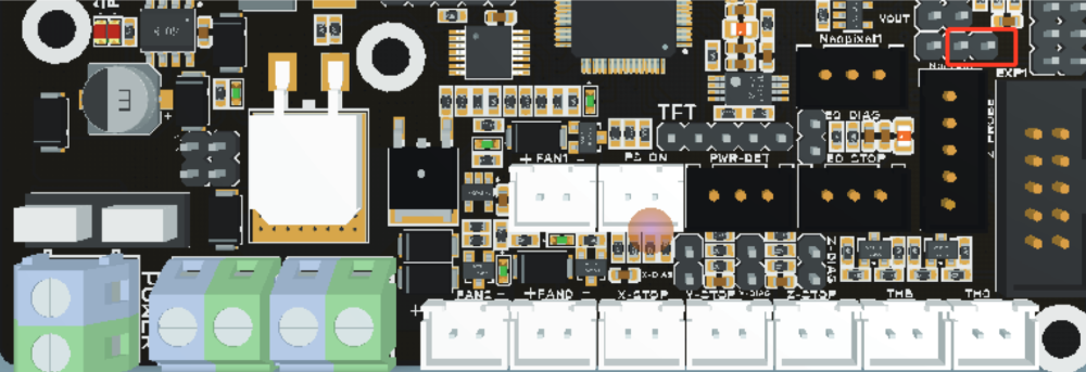
In the case that we do not have it and we use the 5V of the plate:
Firmware
Like almost all Bigtreetech boards, these pay special attention to maximum compatibility and support with the most popular firmwares.
And although the SKR MINI E3 V3 electronics is focused mainly as replacement of original plates of the Creality Ender 3 or Creality Ender 5, this time Bigtreetech very correctly has added direct support for Klipper to its Github repository, great news for sure.
Marlin
We advise you to follow our guide to “cook” your own Marlin that we have in the / Marlin section of our Telegram help bot @ThreeDWorkHelpBot
You can find the sources of the official firmware here.
As we have already mentioned, this electronic board is by default designed to be used in an Ender 3 or 5 and Bigtreetech provides us with the Marlin firmware for these machines already pre-compiled.
Ender-3 Marlin firmware pre-compiled
- firmware-ender3.bin: The original firmware for Ender-3, does not have support for BLTouch
- firmware-ender3-bltouch.bin: Same as above but in this case with BLTouch support
- firmware-ender3-bltouch-for-z-homing.bin: Same as the previous one but in this case configured so that the homing of the Z axis is performed with the BLTouch
Ender-5 Marlin firmware pre-compiled
- firmware-ender5.bin: The original firmware for Ender-5, does not have support for BLTouch
- firmware-ender5-bltouch.bin: Same as above but in this case with BLTouch support
- firmware-ender5-bltouch-for-z-homing.bin: Same as the previous one but in this case configured so that the homing of the Z axis is performed with the BLTouch
If you want to use it for a different machine, we advise you to go through the guide to” cook “your own Marlin , either using as a base the preconfigured ones of your printer or perhaps better using the preconfigured ones for an Ender 3 5 with this plate and adapting the characteristics of our machine.
Anyway, below we will do a specific review for these cases.
Marlin setup for SKR MINI E3 V3
Basically we will have to adjust the 3 Marlin files that are usually used for this purpose. So below we will advise you the values to adjust:
Platformio.ini

In this file we must indicate the chipset that our board has, so we must look at the beginning of the file for the value “env_default” and change it to the following:
default_envs = STM32G0B1RE_btt
/Marlin/configuration.h
Add a comment to any line that we modify since later it will be much easier for us to find our modifications. For this we can add:
In the case that you do not already have a comment, the line
... // 3DWORK
In case you already have a comment
... // 3DWORK ...
We will start by correctly configuring the SERIAL and BAUDRATE for this machine, something key for the correct operation of our TFT, USB or WIFI connection.
#define SERIAL_PORT 2 // 3DWORK E3v3
...
#define BAUDRATE 115200 // 3DWORK E3v3
...
#define SERIAL_PORT_2 -1 // 3DWORK E3v3
Now we will define our MOTHERBOARD which, like we did the platformio.ini, indicates the type of chipset that our board carries and that allows Marlin to use one pin configuration or another.
#ifndef MOTHERBOARD
  #define MOTHERBOARD BOARD_BTT_SKR_MINI_E3_V3_0 // 3DWORK E3v3
#endif
We will define the number of extruders and the diameter of the filament that our printer uses, which basically indicates its diameter. Normally printers use 1.75mm filament although another more or less standard measure is 3mm.
// This defines the number of extruders
// :[0, 1, 2, 3, 4, 5, 6, 7, 8]
#define EXTRUDERS 1

// Generally expected filament diameter (1.75, 2.85, 3.0, ...). Used for Volumetric, Filament Width Sensor, etc.
#define DEFAULT_NOMINAL_FILAMENT_DIA 1.75
Thermistors, in these variables we will indicate which thermistors we have. We advise you to identify which one is yours or, failing that, use one of value 1 which is usually the most normal.
It is very important to indicate the correct type of thermistor so that the measurements that Marlin receives are correct to avoid extrusion problems and/or reading errors.
In the event that we want to deactivate or activate the heated bed, we will comment or activate the thermistor of the bed. In this way we indicate to Marlin whether or not he has a hot bed.
In our example and for this board we will use a hotend and a heated bed with a standard temperature sensor.
#define TEMP_SENSOR_0 1 // 3DWORK E3v3 TE0
#define TEMP_SENSOR_1 0
#define TEMP_SENSOR_2 0
#define TEMP_SENSOR_3 0
#define TEMP_SENSOR_4 0
#define TEMP_SENSOR_5 0
#define TEMP_SENSOR_6 0
#define TEMP_SENSOR_7 0
#define TEMP_SENSOR_BED 1 // 3DWORK E3v3 TB
#define TEMP_SENSOR_PROBE 0
#define TEMP_SENSOR_CHAMBER 0
#define TEMP_SENSOR_COOLER 0
#define TEMP_SENSOR_BOARD 0
#define TEMP_SENSOR_REDUNDANT 0
PID, another very important part is the PID of which you can obtain more detailed information in the /Calibration/Calibration Initial section of our help bot in Telegram @ThreeDWorkHelpBot or in our calibration guide.
Basically the PID helps Marlin to adequately control the temperature without having large fluctuations.
#define PIDTEMP // 3DWORK PID
#define PIDTEMPBED // 3DWORK PID
ENDSTOPS or limit switches, it is important to verify when we change the electronics and turn on for the first time that the logic of the limit switches is correct using the command M119 from a terminal like Pronterface.
This is OPEN in normal state and TRIGGERED when they are pressed. We can reverse this logic by changing:
#define X_MIN_ENDSTOP_INVERTING false // Set to true to invert the logic of the endstop.
#define Y_MIN_ENDSTOP_INVERTING false // Set to true to invert the logic of the endstop.
#define Z_MIN_ENDSTOP_INVERTING false // Set to true to invert the logic of the endstop.
#define X_MAX_ENDSTOP_INVERTING false // Set to true to invert the logic of the endstop.
#define Y_MAX_ENDSTOP_INVERTING false // Set to true to invert the logic of the endstop.
#define Z_MAX_ENDSTOP_INVERTING false // Set to true to invert the logic of the endstop.
#define Z_MIN_PROBE_ENDSTOP_INVERTING false // Set to true to invert the logic of the probe.
On the other hand and although the normal thing is that the machines make the home in MIN (lower left corner) instead of MAX (upper right corner), using HOME_DIR for this change -1 (MIN) 1 (MAX), we must remember that in In the case of changing the logic, enable the corresponding limit switches:
#define USE_XMIN_PLUG
#define USE_YMIN_PLUG
#define USE_ZMIN_PLUG
//#define USE_XMAX_PLUG
//#define USE_YMAX_PLUG
//#define USE_ZMAX_PLUG
Drivers, as we have already mentioned, this board has 4 TMC2209 UART drivers:
#define X_DRIVER_TYPE  TMC2209 // 3DWORK DRIVERS
#define Y_DRIVER_TYPE  TMC2209 // 3DWORK DRIVERS
#define Z_DRIVER_TYPE  TMC2209 // 3DWORK DRIVERS
//#define X2_DRIVER_TYPE A4988
//#define Y2_DRIVER_TYPE A4988
//#define Z2_DRIVER_TYPE A4988
//#define Z3_DRIVER_TYPE A4988
//#define Z4_DRIVER_TYPE A4988
//#define I_DRIVER_TYPE  A4988
//#define J_DRIVER_TYPE  A4988
//#define K_DRIVER_TYPE  A4988
#define E0_DRIVER_TYPE TMC2209 // 3DWORK DRIVERS
//#define E1_DRIVER_TYPE A4988
//#define E2_DRIVER_TYPE A4988
//#define E3_DRIVER_TYPE A4988
//#define E4_DRIVER_TYPE A4988
//#define E5_DRIVER_TYPE A4988
//#define E6_DRIVER_TYPE A4988
//#define E7_DRIVER_TYPE A4988
STEPS or motor steps, with these values we will indicate to Marlin the motor steps to perform movements. In this example we will use the ones that an Ender printer carries by default.
#define DEFAULT_AXIS_STEPS_PER_UNIT { 80.00, 80.00, 400.00, 93 } // 3DWORK Steps for Ender3 axis (X, Y, Z, Extruder)
S_CURVE_ACCELERATION, this functionality offers a great improvement in print quality by smoothing acceleration or deceleration when the print head is in motion.
#define S_CURVE_ACCELERATION // 3DWORK IMPROVEMENTS
PROBE or leveling sensor, we have already commented there is a detailed guide on how to install a BLTouch sensor. We are going to carry out a review of the most important parts to take into account in the event that we want to install a leveling sensor, something highly advisable to ensure that our prints always have the most perfect first layer possible.
We will start by indicating where our leveling sensor is connected, in this case we will connect it to the dedicated PROBE connector.
#define USE_PROBE_FOR_Z_HOMING // 3DWORK PROBE we indicate to Marlin that our sensor is connected in PROBE
#define USE_PROBE_FOR_Z_HOMING // 3DWORK PROBE we tell Marlin that we will use the sensor for the homing of the Z axis
Sensor type BLTouch or Inductive, there are different types of sensors. Depending on the one used, we will have to uncomment one or the other.
In the case of an Inductive sensor:
#define FIX_MOUNTED_PROBE // 3DWORK PROBE
In the case of a BLTouch type sensor:
#define BLTOUCH // 3DWORK PROBE
Sensor offsets, it is very important to tell Marlin where exactly our leveling sensor is installed. We will do this by defining the PROBE OFFSETs.
The Offset is the distance between the tip of the nozzle and the tip of the leveling sensor, which depending on where it is must be positive or negative values, you can use the following graph as an example of what value to put in each case.
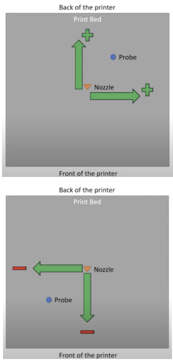
In our case and as an example, our sensor is displaced to the left of the nozzle in X 40mm and 10mm in Y since it is that distance towards the bottom of the printer that are the values of the Creality kit for these machines.
#define NOZZLE_TO_PROBE_OFFSET { -40, -10, -1.85 } // 3DWORK PROBE
PROBING_MARGIN (in previous versions MIN_PROBE_EDGE ), it is very normal that we have a glass as a printing base in our printers although personally we like more magnetic PEI sheets that although being a little more susceptible to being marked with blows have excellent adhesion, it does not limit the size of the bed and removing the pieces is extremely simple and fast.
In any case, we already have glass or another surface, it is advisable that the sensor is away from any object that may bother it during the leveling process, be it staples to fix the glass or the mismatch of the beginning and end of the bed that makes the sensor cannot measure.
For this we will use this PROBING_MARGIN in which we will tell you how many millimeters to move away from the edges of the bed.
In our case using a BLTouch and a PEI platform we leave it by default.
#define PROBING_MARGIN 10 // 3DWORK PROBE
Direction of motors, another very common problem when starting a printer is that the wiring of the coils of our motors does not coincide and there can be two cases:
- That the connectors of our coils are mixed, it is very easy to identify since the motor will not rotate correctly and will stumble. To solve this, it is advisable to check the pinout of the old plate and / or the motor and compare it with that of our new plate to make sure that they match
- That the motor rotates in the wrong direction. In this case again we have two options. First one and recommended is to modify the motor rotation in Marlin and the second is to reverse the wiring of one of the motor coils
In our case we opt for the first one by modifying the following lines in Marlin changing the current value on the contrary … in this case we invert the Z axis.
#define INVERT_X_DIR true
#define INVERT_Y_DIR true
#define INVERT_Z_DIR false // 3DWORK We reverse the rotation of the Z axis
Print size, if we have used a generic Marlin it is important to verify that the print dimensions are correct for our machine.
For the bed size in the example we use an Ender 3 at its maximum size, it is advisable to verify that you can physically reach these measurements and adjust it if necessary:
#define X_BED_SIZE 235 // 3DWORK BED
#define Y_BED_SIZE 235 // 3DWORK BED
We will also define the size of our Z axis:
#define Z_MAX_POS 250 // 3DWORK BED
Filament sensor, we advise you to review in the section /Improvements/Filament sensor of our help bot in Telegram @ThreeDWorkHelpBot.
#define FILAMENT_RUNOUT_SENSOR // 3DWORK FILAMENT SENSOR
As with the limit switches, it is advisable to check the status of the filament sensor with an M119, which should appear TRIGGERED with filament and OPEN without. In the case that it seems inverted we will have to play with the value of (LOW/HIGH):
#define FIL_RUNOUT_STATE LOW // 3DWORK FILAMENT SENSOR
In the case that our filament sensor works by detection of filament flow (like the BigTreeTech Smart Filament Sensor) we must enable the following:
#define FILAMENT_MOTION_SENSOR // 3DWORK FILAMENT SENSOR
Self-leveling, as we mentioned earlier in the /Leveling section of our bot @ThreeDWorkHelpBot you have more detailed information on how to activate UBL self-leveling (the most advanced and recommended for beds of a certain size or with problems) and MESH, that allows you to have a mesh without a sensor by doing the process manually.
In any case, for this example we will enable BILINEAR.
#define AUTO_BED_LEVELING_BILINEAR // 3DWORK PROBE
It is important to tell Marlin to enable self-leveling (G29) after a homing (G28) although in current versions it is no longer necessary but we advise enabling it.
#define RESTORE_LEVELING_AFTER_G28 // 3DWORK PROBE
In the case of BILINEAR, we will specify the number of points to perform per mesh in the next part of Marlin (by default it has 3 points per axis, 3×3 = 9 check points).
if EITHER(AUTO_BED_LEVELING_LINEAR, AUTO_BED_LEVELING_BILINEAR)
// Set the number of grid points per dimension.
#define GRID_MAX_POINTS_X 3 // 3DWORK PROBE
Another function that for safety we must enable is to perform a homing in the center of the bed, this helps us to do two things … the first to ensure that the sensor has a surface to detect the limit switch and the second for visually verify that our Offsets are correct, since the leveling sensor has to be perfectly positioned in the center of our bed.
#define Z_SAFE_HOMING // 3DWORK PROBE
EEPROM, in the EEPROM Marlin saves the configuration values of different functions so that these can be used by the system and be changed by the user without having to modify Marlin source files, compile and upload the firmware at each change. It is highly advisable to activate it and with our SKR MINI E3 V3 we will not have memory problems.
#define EEPROM_SETTINGS // 3DWORK EEPROM
#define EEPROM_CHITCHAT // 3DWORK EEPROM
Nozzle Park, in the example we are explaining we have added a filament sensor. For this to work we must activate NOZZLE_PARK_FEATURE which basically allows us to “park” the print head in a safe area to carry out this filament change, although if we do not have a filament sensor it is highly advisable to have it active as it allows us to improve the pause functions.
#define NOZZLE_PARK_FEATURE // 3DWORK FILAMENT SENSOR
SD, If we want our Marlin to be able to read from our SD either the one on the board or on a compatible screen (note that the Touch is not) we must activate the SD support.
#define SDSUPPORT // 3DWORK SD
Advanced Homing Menu. It is not necessary but it is very advisable in the case of tests to enable this function that allows us to perform a separate homing of each axis.
#define INDIVIDUAL_AXIS_HOMING_MENU // 3DWORK IMPROVEMENTS
Marlin / configuration_adv.h
We have already finished the first part and now we will have to go to the advanced options configuration.
Scroll and long file names, it is interesting to activate this function to be able to show the full name of the files to be printed.
Like the previous one and for it to work correctly we have to activate the following option.
#define LONG_FILENAME_HOST_SUPPORT // 3DWORK IMPROVEMENTS
#define SCROLL_LONG_FILENAMES // 3DWORK IMPROVEMENTS
SD connection, in configuration.h we enable SD Support and in configuration_adv.h we will define where Marlin will try to use that SD from.
We have three options, LCD where we will use that of the Marlin screen. ONBOARD where we will use the one of the electronic board and CUSTOM_CABLE where we will indicate that we use an external reader connected to the electronic board.
As we mentioned previously, not all screens that have SD will work correctly.
#define SDCARD_CONNECTION LCD // 3DWORK SD
Fans, a great success by Bigtreetech is the inclusion of 3 manageable fans.
The definition of the pin of each FAN can be found in the pins file of the board that we have put at the beginning of the article.
FAN0, in this case we are not going to make any changes in its role since it is the layer fan and this is managed by the slicer/laminator itself to cool the filament.
FAN1, in our example we are going to assign it to the hotend so that it is dynamically only activated when the hotend is in operation, avoiding fan wear and unnecessary noise:
#define E0_AUTO_FAN_PIN FAN1_PIN // 3DWORK FAN1 assigned hotend
...
#define EXTRUDER_AUTO_FAN_TEMPERATURE 50 // 3DWORK FAN1 activation at temperature
#define EXTRUDER_AUTO_FAN_SPEED 255 // 255 == full speed
FAN2, to take advantage of this arsenal of manageable fans (we can have more by reusing pins from other functions such as RGB for example) to assign FAN2 as a dynamic electronics fan so that it is activated when the drivers are in use, minimizing wear and noise again by the fan:
#define USE_CONTROLLER_FAN // 3DWORK FAN2 enabled electronic managed ventilation
...
#define CONTROLLER_FAN_PIN FAN2_PIN // 3DWORK FAN2 assigned to electronics
...
#define CONTROLLER_FAN_EDITABLE // 3DWORK FAN2 manageable gcode M710
...
#define CONTROLLER_FAN_MENU // 3DWORK FAN2 enable screen management menu
Babystepping, an almost essential function to have is babystepping. Babystepping allows us to adjust the height of Z during a print to manually adjust this height to our liking.
In our example we will enable that it can be activated with a double click on the button/encoder, which is always available and shows us graphic improvements in the adjustment to understand the direction of the adjustment from the screen.
#define BABYSTEPPING // 3DWORK IMPROVEMENTS
#define DOUBLECLICK_FOR_Z_BABYSTEPPING // 3DWORK IMPROVEMENTS
#define BABYSTEP_ALWAYS_AVAILABLE // 3DWORK IMPROVEMENTS
#define BABYSTEP_ZPROBE_GFX_OVERLAY // 3DWORK IMPROVEMENTS
In case of failure in leveling, another very useful function is to be able to retry the homing process in case of failure. Sometimes our leveling sensor may have a specific failure and through this function it will allow us to try again a finite number of times.
#define G29_RETRY_AND_RECOVER // 3DWORK IMPROVEMENTS
#define G29_MAX_RETRIES 4 // 3DWORK IMPROVEMENTS
ARC support, a substantial improvement in the quality of our prints and also when we print through serial devices such as TFT, Octoprint, etc …
It allows to simplify the gcodes commands, minimizing the number of movements and making them more fluid, also avoiding a large number of retractions.
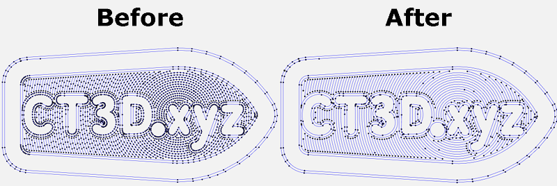
To use it we must configure our slicer/laminator to apply these changes or in the case of Octoprint we can use a plugin. Regarding the changes in Marlin:
#define ARC_SUPPORT // 3DWORK IMPROVEMENTS
It is important to emphasize that in the case of enabling ARC for its use, it is advisable, in the case that we also have it enabled, the compatibility with S_CURVE. You have more information at this calibration guide.
Advanced pause, as we discussed earlier in this example we use a filament sensor. For it to work correctly we have to enable ADVANCED_PAUSE_FEATURE which enables the gcode M600 command to change the filaments.
This can be done with or without a leveling sensor and requires NOZZLE PARK for its correct operation.
#define ADVANCED_PAUSE_FEATURE // 3DWORK FILAMENT SENSOR
Driver configuration, with our TMC2209 drivers in UART we have to correctly configure the advanced parameters that we will find in the HAS_TRINAMIC_CONFIG section.
Micro-steps, although we can configure from 16 to 256 micro-steps, we do not advise you at all to use a value other than 16. With these micro-steps, the definition that we could achieve mechanically is practically impossible to achieve with normal printers. that the TMC drivers already perform the interpolation of these themselves to always offer maximum reliability and precision.
If you desire to read a great article about TMC Drivers not doubt in check this link: TMC Drivers: Discover the best drivers for 3D printing and their available technologies
Speaking of reliability is another important aspect when it comes to micro-steps, the stepper motors that our printers carry lose torque (and steps) at high revolutions so increasing this definition of steps will exponentially increase the reliability percentage and therefore that our pieces do not come out correctly.
In the following example we can see how we have 16 microsteps for our X axis.
#if AXIS_IS_TMC(X)
#define X_CURRENT 650 // (mA) RMS current
#define X_CURRENT_HOME X_CURRENT
#define X_MICROSTEPS 16 // 0..256
#define X_RSENSE 0.11
#define X_CHAIN_POS -1
#endif
Another important value of the previous values is that of CURRENT where we will adjust the current of our motors. You can also adjust them from the LCD from Settings/Advanced/TMC along with other options that we will explain below.
STEALTHCHOP, it is important to enable it if we want our motors to be “silent” since if they will not be working in SpreadCycle mode, which is the power mode.
#define STEALTHCHOP_XY // 3DWORK DRIVERS
#define STEALTHCHOP_Z // 3DWORK DRIVERS
#define STEALTHCHOP_E // 3DWORK DRIVERS
Although rare, some extruders may work better with StealthChop mode disabled. If this is our case, we will comment on the following line.
//#define STEALTHCHOP_E // 3DWORK DRIVERS
CHOPPER TIMMING, is used by StealthChop for the synchronization of signals to the motors. This has to match the voltage used in our printer, in the case of Ender 3 and normally in all 24v printers.
#define CHOPPER_TIMING CHOPPER_DEFAULT_24V // 3DWORK DRIVERS
Monitor Status, this function allows Marlin to control in detail all the parameters of the drives to be able to adjust, for example, their temperature to avoid more serious problems.
#define MONITOR_DRIVER_STATUS // 3DWORK DRIVERS
Hybrid Threshold, another interesting function is Hybrid Threshold that allows Marlin to switch between StealthChop (silence) or SpreadCycle (power) dynamically based on the speed of movements.
#define HYBRID_THRESHOLD // 3DWORK DRIVERS
#define X_HYBRID_THRESHOLD 100 // [mm/s]
#define Y_HYBRID_THRESHOLD 100
#define Z_HYBRID_THRESHOLD 15
In our case we use the values indicated for an Ender which are 100mm / s for X Y and 15 for Z although we can adjust it to our needs.
TMC Debug, in this case it is a MONITOR_DRIVER_STATUS requirement that we must enable and will allow us to have the M122 command accessible, very useful for obtain advanced information on the status and configuration of our drivers.
#define #define TMC_DEBUG // 3DWORK DRIVERS
Pin file of our SKR MINI E3 V3
The pins file containing the references for this board can be found in the Marlin firmware, at the following path: Marlin/src/pins/stm32g0/pins_BTT_SKR_MINI_E3_V3_0.h
Update Marlin firmware
In this case it is very simple and we just have to copy our firmware.bin to the root of the SD formatted in FAT32, insert the SD in the module slot and wait about 30 seconds for finish the process.
Once done, the firmware.bin file must be renamed to firmware.CUR, which we can save as a backup (remember that a compiled firmware cannot be modified, this process only it can be done with the source files of your firmware and recompiled).
Klipper
Klipper is an open-source firmware for our 3D printers that use the power of a Raspberry Pi, normally although it can be mounted on many more devices, to control the electronics of your printer. By doing this we can make it work faster and with more precision depending on the system and hardware we have in our 3D Printer.
Something that Klipper will allow us in any case is to be able to have a lower level control of our machine, which will also require extra knowledge/efforts, a greater speed when applying any changes and a first-class remote control of our machine (hardware).
It is important to emphasize that if we come from other systems, Klipper may have some restrictions regarding compatibility with components or with certain functions that we have already in our printer.
On the other hand, we have very interesting control functions of our printer such as Pressure Advance (similar to Marlin’s Linear Advance) and Input Shaper which will greatly improve speed and quality.
Raspberry Pi connection to our SKR MINI E3 V3
As we have already mentioned, the heart of Klipper runs in a Raspberry Pi normally, we can connect using a USB cable or via USART to our SKR MINI E3 v3 but for our example we will use the most common/simple one which is using a USB cable.
Klipper firmware generation
In order for Klipper to control our SKR MINI E3 V3, it must contain a firmware which we can obtain in different ways:
- Using the precompiled firmwares that we can find on the Bigtreetech github
- firmware-USB.bin in the case that we use the connection between our Klipper and SKR MINI E3 v3 via USB
- firmware-USART2.bin in this other case we will use the connection USART2 to communicate both components.
- Compiling our firmware
- We can follow the official Klipper documentation to install it we also recommend using Kiauh, Fluidd Pi or MainsaiOS have images that greatly facilitate the installation process of all the necessary components. You can review our Klipper Guide.
- Following the previous documentation we will go to the option Building the microcontroller using this configuration:
- [*] Enable extra low-level configuration options
- Micro-controller Architecture = STMicroelectronics STM32
- Processor model = STM32G0B1
- Bootloader offset = 8KiB bootloader (stm32duino)
- Clock Reference = 8 MHz crystal
- If we use USB
- Communication interface = USB (on PA11/PA12)
- If we use USART2
- Communication interface = Serial (on USART2 PA3/PA2) < / li>
The firmware klipper.bin will be generated in the folder home/pi/klipper/out which if Klipper is not able to copy it directly to the SD of our SKR MINI E3 V3 manually copy to SD using WinSCP or the pscp command in CMD.

- Updating our SKR MINI E3 V3 to Klipper firmware, it will be enough to rename the firmware created / downloaded firmware-USB.bin, firmware-USART2.bin or klipper.bin to fiwmware.bin, which is the default name used by our Octupus bootloader to make the. update process.
Klipper basic configuration
- Using as reference official Klipper documentation to install it to configure Klipper we will use the configuration SKR MINI V3 klipper.cfg as the basis for our printer.cfg which includes the correct pinning level definitions for our SKR MINI E3 V3.
- You can use the Klipper configuration documentation to enable the functions that interest us most.
- If we are going to use USB to communicate Klipper with SKR MINI E3 V3 we will execute the following command from Klipper ls/dev/serial/by-id/*, from Kiauh available. We can quickly and easily execute this action from its menu, to identify the correct ID of our SKR MINI E3 V3 and add it to our printer.cfg.

...printer.cfg
[mcu]
serial: /dev/serial/by-id/usb-Klipper_stm32g0b1xx_4D003C000B50345033313820-if00
- If we use USART2 to communicate we will need to modify some settings on our Raspberry Pi directly on the SD from the computer or in the most comfortable and advisable way that is through SSH.
- Delete or comment the line console = serial0,115200 in /boot/cmdline.txt
- Add dtoverlay=pi3-miniuart-bt to the end of /boot/config.txt
- Modify the configuration[mcu] in printer.cfg to serial:/dev/ttyAMA0 and enable restart_method:command
...printer.cfg
[mcu]
serial: /dev/ttyAMA0
restart_method: command
Configuration of UI Klipper for LCD/TFT
To enable the Klipper UI for LCD / TFT screens we have the following examples:
BigTreeTech’s dual TFTs are all-rounders and the best screens for our printers have a perfect emulation mode to use in Klipper. To enable them we will configure the [display] section in printer.cfg as follows:
[display]
lcd_type: emulated_st7920
spi_software_miso_pin: PD8 # status led, Virtual MISO
spi_software_mosi_pin: PD6
spi_software_sclk_pin: PB9
en_pin: PB8
encoder_pins: ^PA10, ^PA9
click_pin: ^!PA15

[output_pin beeper]
pin: PB5
Final notes
Now we only have to compile, adjust any error that the compiled report reports to us and put it on our electronic board. And of course, we advise you to initially verify the printer as follows:
- Check limit switches using a terminal (Pronterface for example) with the M119 command.
- Check individually Homing of each of the movement axis in order (XYZE) and reverse motor rotation if is necessary.
- Check that our thermistors reports the temperature correctly.
- Check that our heatbed and hotend heaters work correctly and without any issue.
- Carry out the Initial Calibration guide that you can find in our bot in the /Calibration section.
As always, we hope that the article has been useful for the configuration of these new electronic boards BigTreeTech SKR MINI E3 V3. You can leave your comments or doubts at the end of it.
You can find other interesting articles in the following links:
- Ratrig VCore3: Review, guide and configuration of a DIY printer that touch the perfection
- BTT Octopus Pro: Natural evolution of Octopus for high performance and speed machines
- The best resin 3D printers in 2021
- Longer LK5 Pro: Review of a High-Volume Desktop 3D Printer
- Nozzle: Learn all the basics about this essential component
- Elegoo Mars 2 Pro: Review of a great resin printer for home use
- BTT Octopus: Analysis and Setup Guide with Marlin and Klipper
- FYSETC S6: Complete guide to this excellent electronic board for our 3D printers
- BTT SKR 2: How to detect and repair the failure of the first revisions (REV A)



















Skr mini e3v3 is it a drop in replacement for the ender 5 plus??? Do i need to compile firmware???
Is a stock printer any help will be highly appreciate
Hi Enrique, Bigtreetech provide pre-compiled firmware for Ender 5 but not for 5 plus as is a bit different and special display… this doesn’t mean you cannot use this mainboard but you will need to do some more changes to the firmware, compile and search for modification to use stock display or the better solution change with Bigtreetech display with dual-mode.
There is mistake: board has 5 TMC2209 UART drivers
this board has only 4 drivers
Thanks Wojtek!!! the typo was fixed 🙂
Hi, I want to make my own firmware for this motherboard for an Ender 3 stock. But in Marlin I get this error: Error: Unknown environment names ‘STM32G0B1RE_btt’. Valid names are ‘include_tree’
How can I fix it? I’m in the latest version of Marlin and with the files provided by BTT on their GitHub. thanks in advance.
In case anyones make it, I only want to have the screen in Spannish, that’s all.
As commented by Telegram you should have last stable Marlin version 2.0.9.3 or higher as commented in the guide.
Hi, same problem as Aimar. I donwloaded the latest version of files with Marlyn 2.0.9.3 and when tried to compile in VS I get the followign error:
Error: Unknown environment names ‘STM32G0B1RE_btt’. Valid names are ‘include_tree’
any help? Thanks in advance
The environment is the correct one since 2.0.9.3 Marlin original.
Try to use the original Marlin using last stable version 2.1.0.
Will the compiled factory firmware work out of the box with the cr10s? I have a bltouch and want to add this controller along with the tft 35
https://github.com/MarlinFirmware/Marlin/releases/tag/2.1
Build / Upload
BTT STM32G0B1RE xfer build (#24245)
I am compiling Marlin firmware for BTT SKR Mini E3 V3 with LCD by BTT Mini 12864 V1.0
I am using VSCode for the modifications and getting compilation errors as follows:
DOGLCD_CS’ was not declared in this scope; did you mean ‘DOGLCD_SCK’?
DOGLCD_A0′ was not declared in this scope; did you mean ‘DOGLCD’?
These two pins are already specified in the file — pins_BTT_SKR_MINI_E3_V3_0.h But the above errors are found in Marlinui_DOGM.cpp file
Can you please tell me any solution for this? I am a beginner in programming…
So much hype about the BTT SKR MINI E3 V3 and how great it is on Ender 3 printers but your Marlin Builder doesn’t even have the processor model needed to create environment for Ender 3 V2 (BTT STM32G0B1RE). Sounded like your builder was going to make this so easy to do but it’s not even an option. MAJOR disappointment!
Thanks Nathan for your comments in any case… Why you related o evaluate the quality for a mainboard based on if is supported or not by our Marlin builder.
First this is a hobby for us and adapt and implement the Marlin Builder is a huge amount of effort and time we not always have to dedicate to update, in any case you see the version used on Marlin Builder and inside the guide the version support this mainboard from Marlin.
However you can visit the Bigtreetech GitHub repository to download official images, use our Compiling Marlin guide and this one to create manually yourself… Basically the same as do our Marlin Builder… Choose a preconfigured Marlin config, overwrite base config files and update the platfoemio.ini files… All the information needed in the review.
And again evaluate this mainboard based on if our Marlin Builder support it or not seems really vague evaluate for a really good and powerful mainboard.
Great guide guys, my 2nd e3v3 on my other ender5pro
Too lazy to open up my other printer to confirm the wiring, but the klipper config was easy as always once you have the default settings
Thanks again
Dammit forgot to add a 5*
good job
hi, i have installed this board but have a problem. the power led is on but the status led is remaing blinking even with everything disconnected. compiled firmware. what could be ?
Hi, I get into trouble. My Ender 3 v2, when I installed andconnected my bl touch does work. I put the new software frrom github, but still does not work. How can i connect my bl touch if it has only white, brown, yellow, red and blue cables for bltouch?
My BlTouch doesn’t work, so how can I connect my wires, and where I have to connect them?
You can review our technical guide for bltouch sensors here https://marlin-3dwork-io.translate.goog/marlin/configuracion-marlin/nivelacion/bltouch-3dtouch?_x_tr_sl=es&_x_tr_tl=en&_x_tr_hl=es&_x_tr_pto=wapp
In any case you can join our Telegram channel to provide more information