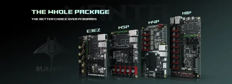
The new Bigtreetech Manta series, which has four versions to adapt to any machine, as well as having some very interesting improvements and new features that we have been testing for weeks.

If you need more information or help, feel free to join the SKR Telegram group or our general 3DWork group.
Bigreetech Manta Series Specs
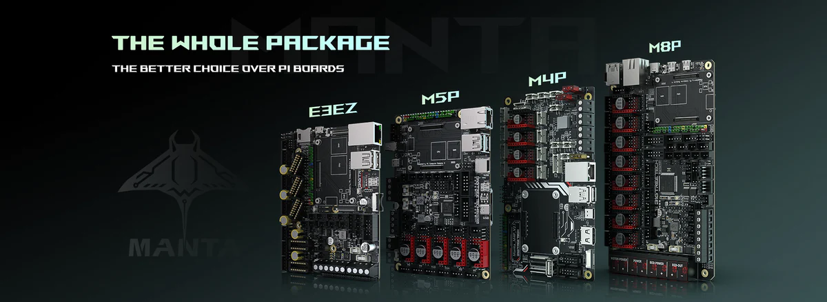
The new Bigtreetech Manta series currently has four versions with different formats, in the following video you can see a brief introduction.
Common Features
- Options for use with different types of displays, we have an HDMI port available in addition to using an SPI display. On the other hand, we also have a DSI/CSI connector for the use of screens/cameras with this interface
- Expansion options, we have specific connectors designed to expand functionalities such as filament sensors, leveling sensors, neopixel LED strips, UPS or Relay modules, etc…
- Support for different types of drivers, wide support for different models/types of drivers such as TMC5160, TMC2209, TMC2225, TMC2226, TMC2208, TMC2130, ST820, LV8729, DRV8825, or A4988. In addition to supporting different operating modes with them such as UART/SPI smart modes or traditional STEP/DIR modes.
Main Differences Between Versions
- Different MCU, while the Manta M4P mounts an ARM Cortex-M0+STM32G0B0RE 64MHz the Manta M8P uses a slightly improved version of ARM Cortex-M0+STM32G0B1VET6 64MHz which in any case is going to have more than enough performance in use with both Marlin and Klipper.
- Fan ports, for use in cooling electronics, motors, drivers, or any other device
- With the Manta M8P we have an arsenal of fan ports: 4 of them with two standard pins (PWM) (FAN0, FAN1, FAN2, FAN3), 3 with four pins (tachometer) (FAN4, FAN5, FAN6)… all controllable from firmware as well as having voltage selection between 5-12-24V… and two non-controllable with constant power.
- with the Manta M4P we have 3 them controllable two-pin with 5-24V voltage selection
- Ports for drivers, another difference between the two electronics is the number of interfaces available for drivers
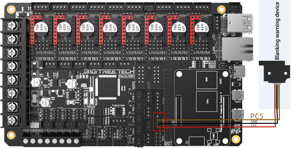
- The Manta M8P has 8 sockets counting one of them (Motor2) with a double interface for the connection of two motors in the same driver, normally used in Z motion axes
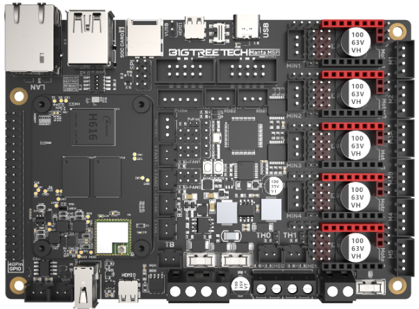
- On the other hand, the Manta M4P has 4 sockets, the Z being dual for the connection of two motors in the driver
| M8P v2.x | M8P v1.x | M5P | M4P | |
| MCU | STM32H723ZET6 | STM32G0B1VET6 | STM32G0B1RET6 | STM32G0BORE |
| Frequency | 550 MHz | 64 MHz | 64 MHz | 64 MHz |
| Driver Slots | 8 | 8 | 5 | 4 |
| eFuse | Yes | Yes | Yes | No |
| Fan Ports | 2 PWM Fan x 5 4pins PWM Fan x 2 Always on Fan x 1 SoC Fan x 1 | 2 PWM Fan x 5 4pins PWM Fan x 2 Always on Fan x 1 SoC Fan x 1 | PWM Fan x 2SoC Fan x 1 Always on Fan x 1 | PWM Fan x 4SoC Fan x 1 |
| Fan Voltage Selection | Yes, 24V/12V/5V | Yes, 24V/12V/5V | Yes, 24V/12V/5V | Yes, Vin/5V |
| Voltage Drivers | 24V, HV (selectable) | 24V, HV (selectable) | 24V, HV (selectable) | 24V, HV (selectable) |
| Electronic Voltage | VIN=DC12V or DC24V | VIN=DC12V or DC24V | VIN=DC12V or DC24V | VIN=DC12V or DC24V |
| HotBed Voltage | VIN=DC12V or DC24V or BEDIN | VIN=DC12V or DC24V or BEDIN | VIN=DC12V or DC24V | VIN=DC12V or DC24V |
| Heater Ports | Heated Bed (HB) 10A, Heater Catridge (HE0, HE1, HE2, HE3) 5.5A | Heated Bed (HB) 10A, Heater Catridge (HE0, HE1, HE2, HE3) 5.5A | Heated Bed (HB) 10A, Heater Catridge (HE) 6A | Heated Bed (HB) 10A, Heater Catridge (HE) 6A |
| Ventilators | 2-pin controllable (FAN0, FAN1, FAN2, FAN3), 4-pin controllable (FAN4, FAN5, FAN6), all controllable with voltage selection 5-12-24Vfixed (24V FAN*2) up to 1A | 2-pin controllable (FAN0, FAN1, FAN2, FAN3), 4-pin controllable (FAN4, FAN5, FAN6), all controllable with voltage selection 5-12-24Vfixed (24V FAN*2) up to 1A | three controllable (24/5V adjustable), one for SoC (non-selectable voltage) Up to 1A | two controllable (24/5V adjustable), one for SoC (non-selectable voltage) Up to 1A |
| Expansion Ports | BL Touch (Servos, Probe), PS-ON, Fil-DET, RGB*2, SPI | BL Touch (Servos, Probe), PS-ON, Fil-DET, RGB*2, SPI | BL Touch (Servos, Probe), Fil-DET, RGB*2 | BL Touch (Servos, Probe), Fil-DET, RGB*2 |
| Supported Drivers | Support TMC5160, TMC2209, TMC2225, TMC2226, TMC2208, TMC2130, ST820, LV8729, DRV8825, A498 | Support TMC5160, TMC2209, TMC2225, TMC2226, TMC2208, TMC2130, ST820, LV8729, DRV8825, A498 | Support TMC5160, TMC2209, TMC2225, TMC2226, TMC2208, TMC2130, ST820, LV8729, DRV8825, A498 | Support TMC5160, TMC2209, TMC2225, TMC2226, TMC2208, TMC2130, ST820, LV8729, DRV8825, A498 |
| Driver Modes | SPI, UART, STEP/DIR | SPI, UART, STEP/DIR | SPI, UART, STEP/DIR | SPI, UART, STEP/DIR |
| Thermistors | 5*100K NTC, 4 of them 100K NTC and PT1000 selectable | 5*100K NTC, 4 of them 100K NTC and PT1000 selectable | 2*100K NTC | 2*100K NTC |
| Supported Displays | SPI, DSI, HDMI, LCD Display (EXP1+EXP2) | SPI, DSI, HDMI, LCD Display (EXP1+EXP2) | SPI, DSI, HDMI, LCD Display (EXP1+EXP2) | SPI, DSI, HDMI, LCD Display (EXP1+EXP2) |
| USB | Type-C | Type-C | Type-C | Type-C |
| Other Interfaces | USB2.0*3, LAN, DSI, CSI, SPI, 40Pin-GPIO, HDMI0 and HDMI1, SOC_Card, MCU-Card | USB2.0*3, LAN, DSI, CSI, SPI, 40Pin-GPIO, HDMI0 and HDMI1, SOC_Card, MCU-Card | USB2.0*3, LAN, DSI, CSI, SPI, 40Pin-GPIO, HDMI, SOC_Card, MCU-Card | USB2.0*3, LAN, DSI, CSI, SPI, 40Pin-GPIO, HDMI, SOC_Card, MCU-Card |
CB1 Module
Very rightly, considering the current price of the Raspberry Pi, along with the launch of the Manta series by Bigtreetech has released its CM4 module called CB1.

The CB1 is an electronic device that includes a CPU, RAM, Wifi module, and other components in the form of a “mini” PC.
With an Allwinner H616 CPU, used in other similar Orange Pi electronics, which internally has a 64b ARM Quad-core Cortex-A53 processor as well as 1GB of RAM and of course 100M network support both ethernet and WiFi.
| Text | CB1/CB1 eMMC |
|---|---|
| CPU | ALLWINNER H616, Quad-core Cortex-A53 @1.5GHz |
| GPU | Mali G31 MP2, Support OpenGL3.2 |
| RAM | 512MB/1GB DDR3L SDRAM The eMMC version has only 1GB available |
| Storage Capacity (for eMMC version only) | 16GB, 32GB |
| WiFi | 2.4G/802.11 b/g/n |
| Display | Compatible with HDMI2.0A Interface, Support 4K Displays |
| Connectivity | USB2.0 Interface, supports 100M Ethernet+ 100M WiFi The CB1/CB1 eMMC does not support DSI/CSI output at this time |
With these features, we can run Klipper without much trouble.
The combination of the Manta series together with the CB1 module will allow us to have a complete, modular, and powerful solution as an example:


In addition, we also have the Pi4B module that together with the CB1 we are going to have a format and functions similar to a Raspberry Pi 4B.

Connections
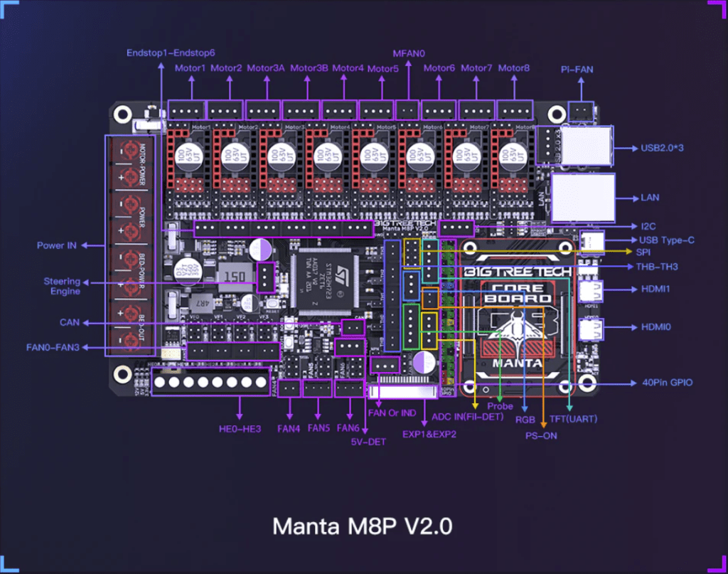
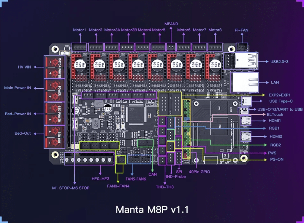
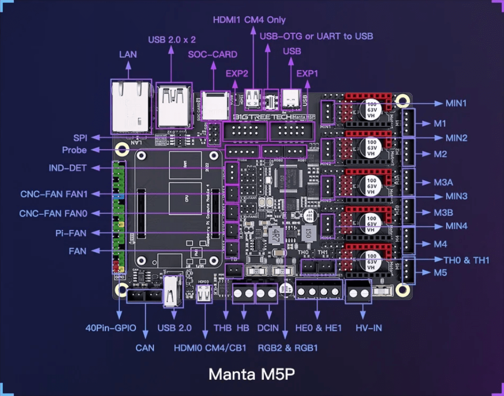
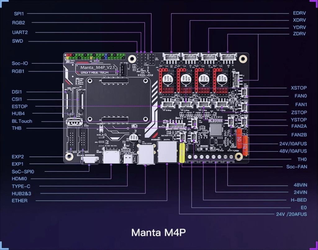
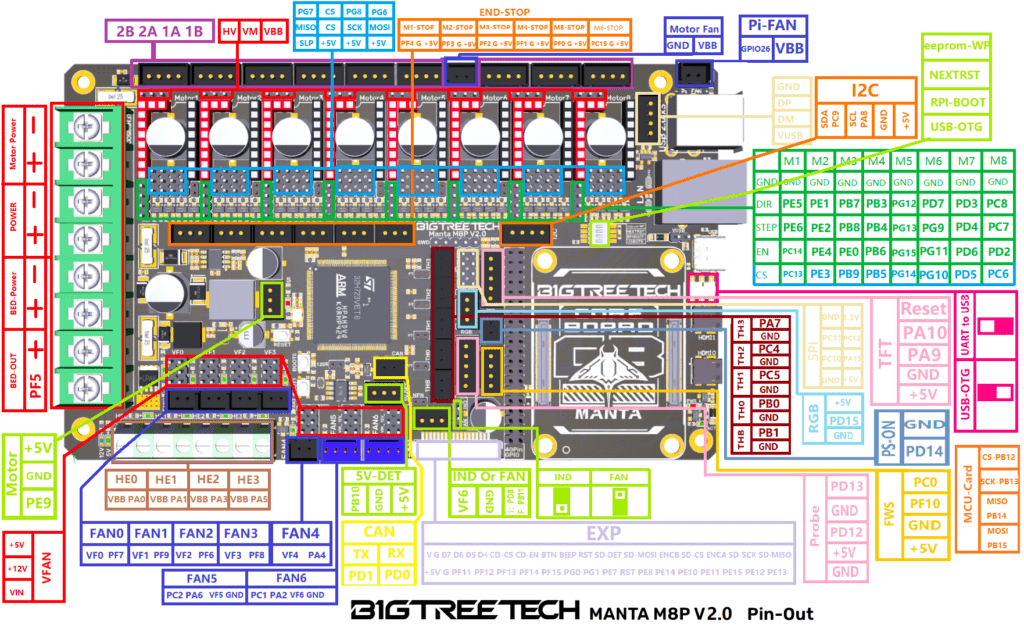
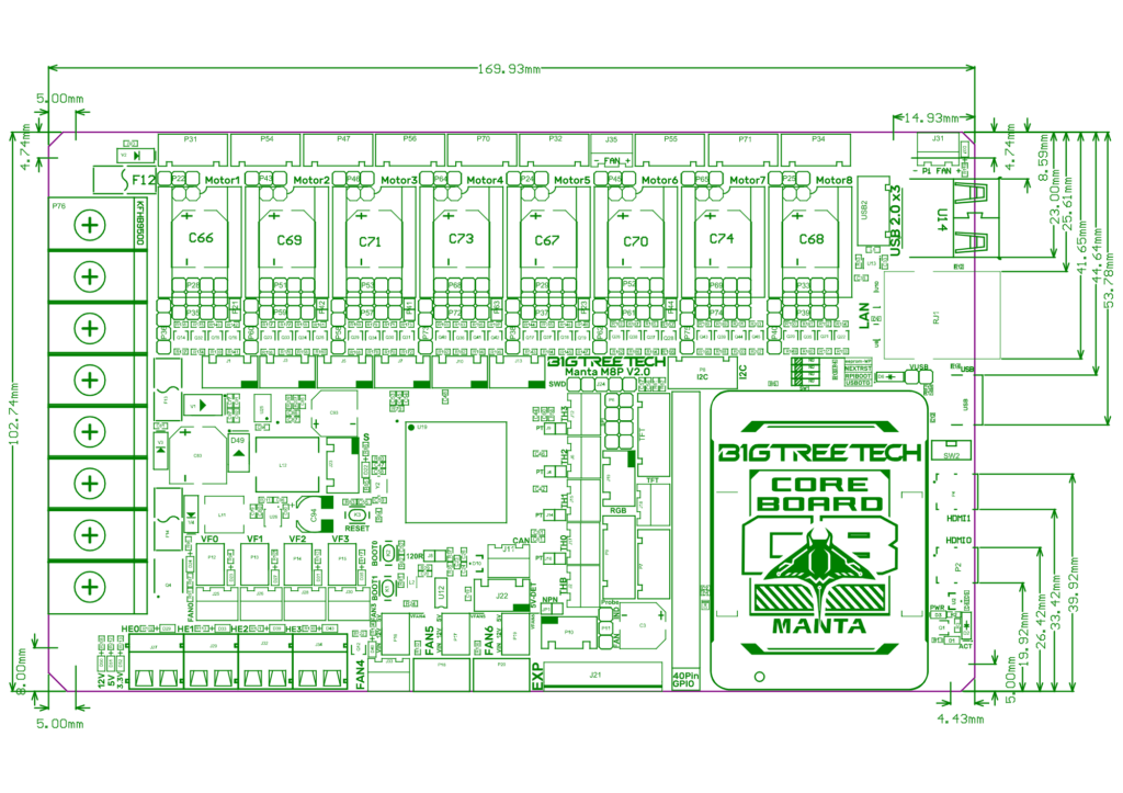
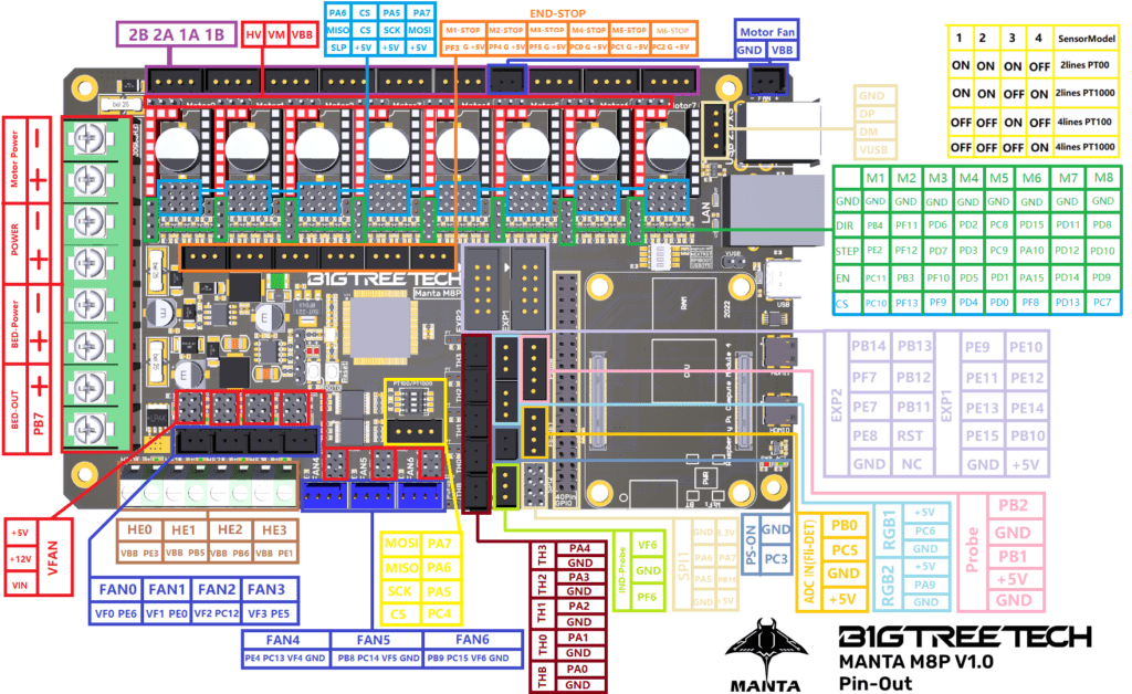
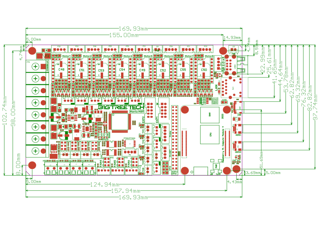
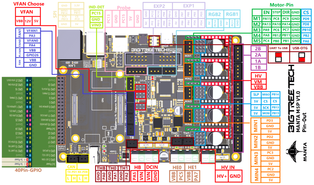
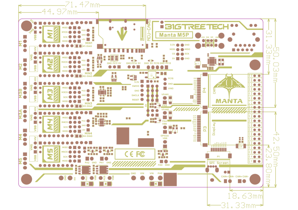
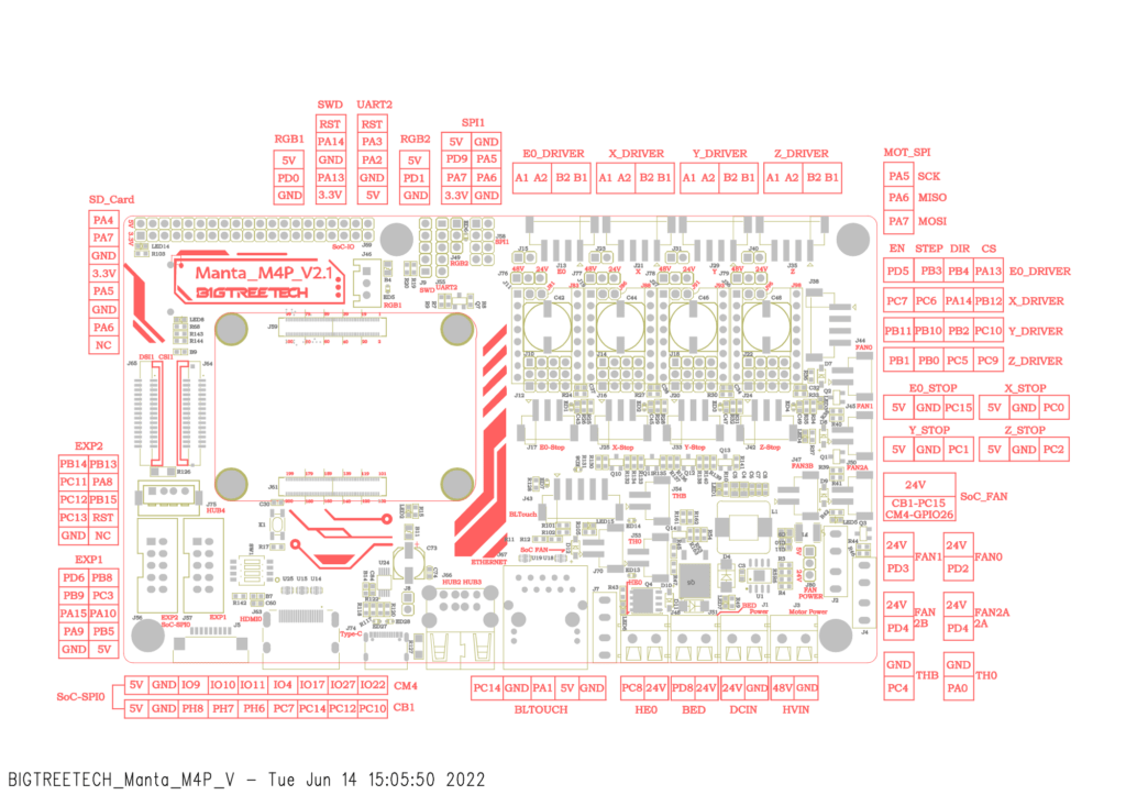
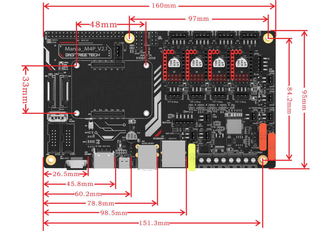
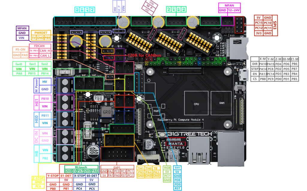
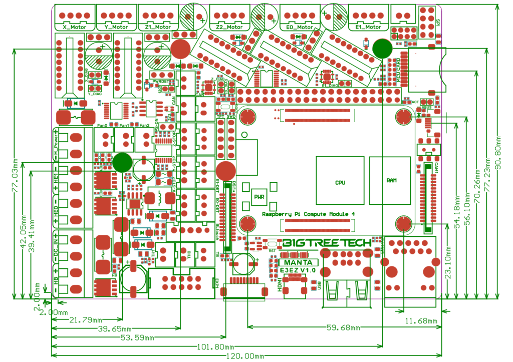
As always in our guides we like to share the diagrams and diagrams, to be able to see in more detail both electronics and their connections.
Bigtreetech has always paid a lot of attention to expansion options as well as accessory compatibility, the Manta range could not be less and we have a good number of connections to offer support to leveling sensors, displays, cameras, CANbus extenders, accelerometers, LED lighting, etc…
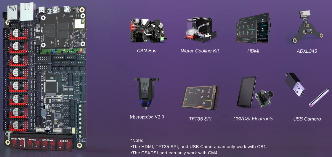
Connection diagrams examples:
Diagrams & Schematics, Bigtreetech Manta Series
We attach the diagrams/diagrams of the Bigtreetech Manta series that will be of great help in the installation/configuration:
Basic Connections
Let’s review the basic connections to keep in mind when we get our Bigtreetech Manta up and running.
Power
We can power our Bigtreetech Manta in two ways, depending on what we want to do with it, either from an external power supply that will be the default way or by USB in those cases that we use it for basic electronics tests or firmware loading.
To select one shape or another, we will do it through a jumper on the VUSB pins of the electronics… with the post, we will tell the electronics that their power is by USB.
Installation of CM4 modules
As we mentioned, one of the great functions of this electronic system is to integrate an internal host to perform the functions of Klipper, Octoprint, etc… To do this, we have a CM4 socket/connector which is a standardized type of connection for the connection of these modules.
Drivers
The Manta series has different configurations to adapt to any machine on the market and one of the differences between the different models is the number of drivers supported.
If we pay attention to the name of the different models, we will quickly identify that through it we will be able to quickly know how many are supported… MxP where X is the number of supported drivers except for the E3EZ.
These electronics support almost any type of drivers (TMC5160, TMC2209, TMC2225, TMC2226, TMC2208, TMC2130, ST820, LV8729, DRV8825, A4988), as well as support for different modes to use them (SPI, UART, STEP/DIR). In the case of the E3EZ, it will use Bigtreetech’s EZ-formatted drivers, which is a format we love.
In case our drivers support it, the ideal is always to use the intelligent SPI/UART management mode, one or the other will depend on the model of drivers we use.
These driver management modes allow the firmware to dynamically manage the driver configuration according to needs, as well as being able to adjust, for example, the vref/current that will be supplied to our motors and other functions available in each driver model.
- UART, is a type of serial communication between the electronics and the firmware to be able to manage the driver… Supported by drivers TMC2208, TMC2209, TMC2225 by way of example. To activate this mode we will simply place the jumper in the position of the following image and make sure that our driver supports and has enabled that mode (although they usually come already prepared sometimes it is necessary to perform a solder or put a jumper in it):

- SPI, another type of communication more advanced than UART because it has more bandwidth and is supported by TMC2130, TMC5160, TMC5161 drivers as examples. As in the previous case, we will enable it by placing jumpers as we see in the following image:

Finally, we have the traditional method or STEP/DIR (STANDALONE) that uses the default settings of the driver, we will have to adjust the view/current of the motors manually and specify the microsteps of it using the appropriate combination of the MS0/MS1/MS2 jumpers. Normally we will use this mode for older A4988, DRV8825, LV8729, ST820 drivers:

In case our drivers support it, the ideal is always to use the intelligent SPI/UART management mode, one or the other will depend on the model of drivers we use.
These driver management modes allow the firmware to dynamically manage the driver configuration according to needs, as well as being able to adjust, for example, the vref/current that will be supplied to our motors and other functions available in each driver model.
- UART, is a type of serial communication between the electronics and the firmware to be able to manage the driver… Supported by drivers TMC2208, TMC2209, TMC2225 by way of example. To activate this mode we will simply place the jumper in the position of the following image and make sure that our driver supports and has enabled that mode (although they usually come already prepared sometimes it is necessary to perform a solder or put a jumper in it):
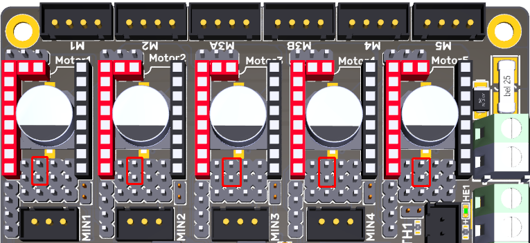
- SPI, another type of communication more advanced than UART because it has more bandwidth and is supported by TMC2130, TMC5160, TMC5161 drivers as examples. As in the previous case, we will enable it by placing jumpers as we see in the following image:
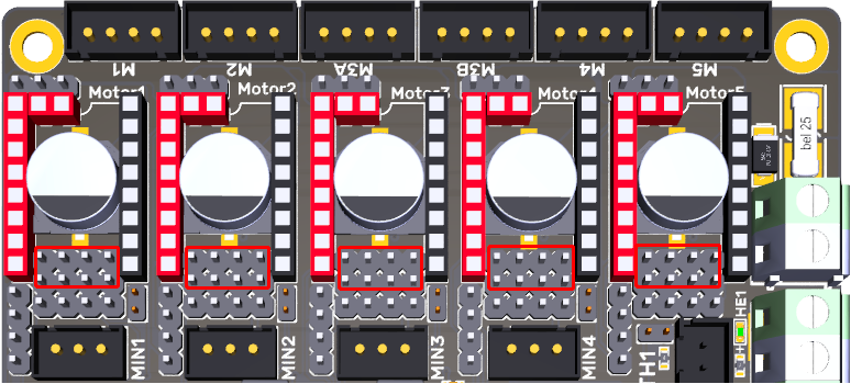
Finally, we have the traditional method or STEP/DIR (STANDALONE) that uses the default settings of the driver, we will have to adjust the vref/current of the motors manually and specify the microsteps of it using the appropriate combination of the MS0/MS1/MS2 jumpers. Normally we will use this mode for older A4988, DRV8825, LV8729, ST820 drivers:

In case our drivers support it, the ideal is always to use the intelligent SPI/UART management mode, one or the other will depend on the model of drivers we use.
These driver management modes allow the firmware to dynamically manage the driver configuration according to needs, as well as being able to adjust, for example, the vref/current that will be supplied to our motors and other functions available in each driver model.
- UART, is a type of serial communication between the electronics and the firmware to be able to manage the driver… Supported by drivers TMC2208, TMC2209, TMC2225 by way of example. To activate this mode we will simply place the jumper in the position of the following image and make sure that our driver supports and has enabled that mode (although they usually come already prepared sometimes it is necessary to perform a solder or put a jumper in it):

- SPI, another type of communication more advanced than UART because it has more bandwidth and is supported by TMC2130, TMC5160, TMC5161 drivers as examples. As in the previous case, we will enable it by placing jumpers as we see in the following image:

Finally, we have the traditional method or STEP/DIR (STANDALONE) that uses the default settings of the driver, we will have to adjust the vref/current of the motors manually and specify the microsteps of it using the appropriate combination of the MS0/MS1/MS2 jumpers. Normally we will use this mode for older A4988, DRV8825, LV8729, ST820 drivers:
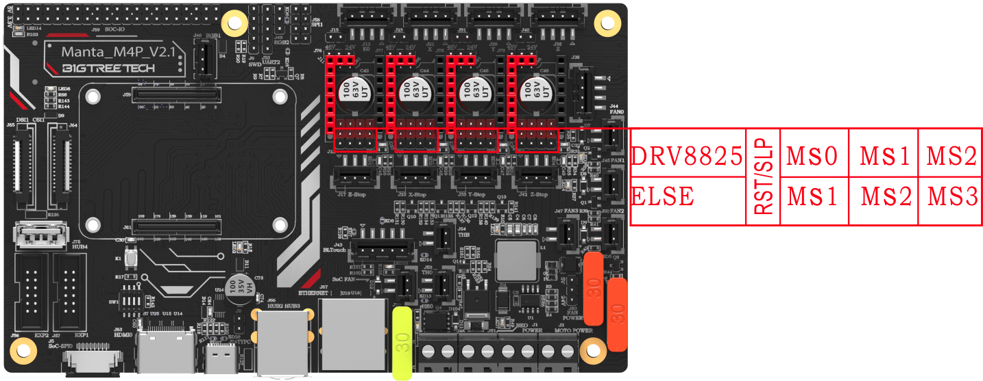
The case of the E3 EZ uses Bigtreetech’s EZ drivers, the E3 EZ supports SPI and UART drivers in parallel without the need for any type of pin adjustment.
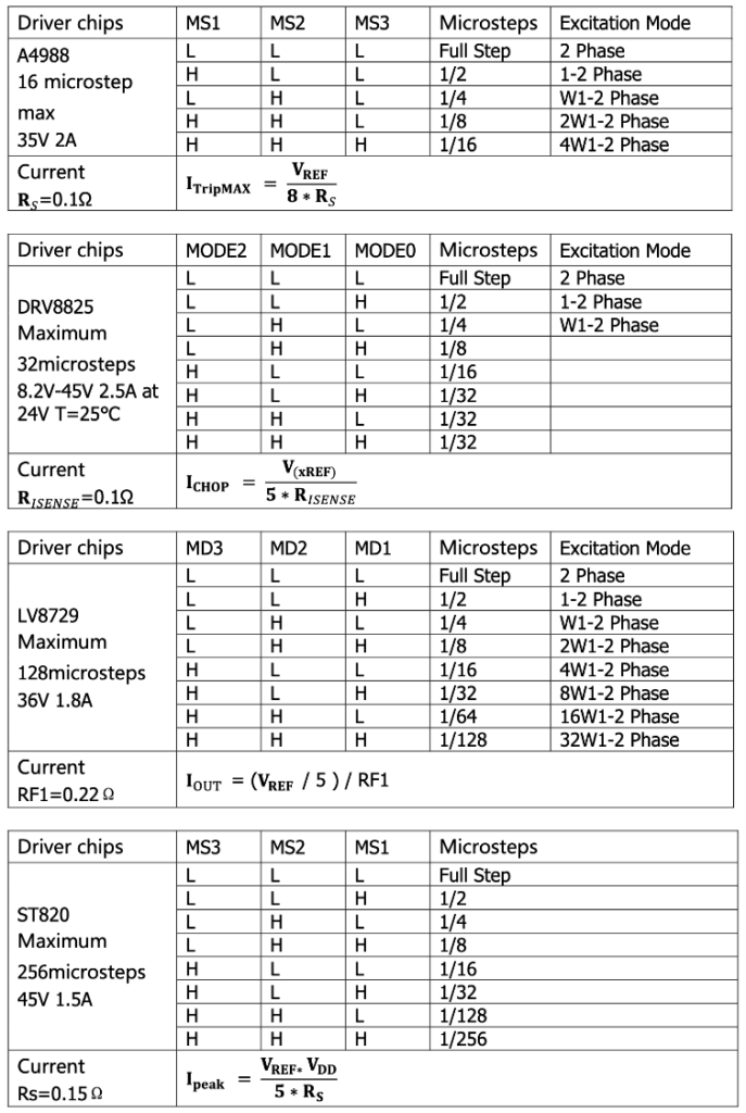
Another option we have is, for those drivers that support it, the use of sensorless… With this functionality, we can simulate a limit switch/endstop and thus not need sensors or wiring for this function.
To activate this function at the level of the electronics, we will do it by connecting the jumpers in the drivers that we want to activate this functionality:
Also, depending on the model, we have a voltage selection to power our motors in those cases where we want to use HV (High Voltage):
For a connection of our drivers/motors to the general power supply (12/24V):

In the case of using HV drivers/motors, we remind you that these electronics support power up to 56V which we will connect to the HV-IN power connection:

For a connection of our drivers/motors to the general power supply (12/24V):
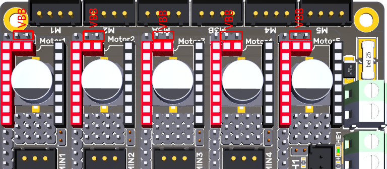
In the case of using HV drivers/motors, we remind you that these electronics support up to 56V:

For a connection of our drivers/motors to the general power supply (12/24V):
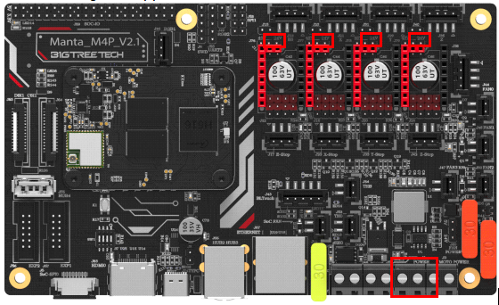
In the case of using HV drivers/motors, we remind you that these electronics support up to 56V:

For a connection of our drivers/motors to the general power supply (12/24V):

In the case of using HV drivers/motors, we remind you that these electronics support up to 56V:

Fans
The different models of Manta have different configurations and options for the connection of layer fans, hotend fans, electronics, or any other use.
We have already seen in the specifications of each model the number of fans supported, how many of these can be managed, and if we have options to define the voltage to be used in them:
In the case of the M8P model, we have:
- 2 Pin PWM Fan x 4
- 4-pin PWM Fan (4-pin PWM fan with tachometer) x 3
We have a 5/12/24V power selection jumper:
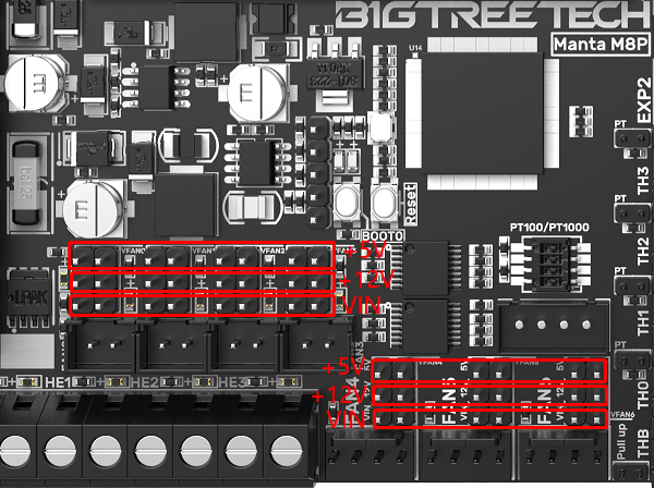
Also for 4-pin fans you have the following connection diagram:
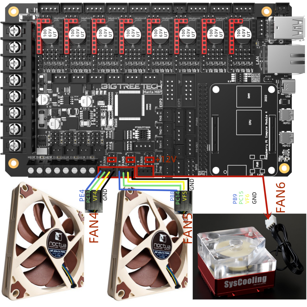
In the case of the M5P model, we have:
- 2 pin PWM Fan x 3
We have a 5/12/24V power selection jumper:

In the case of the M4P model, we have:
- 2 pin PWM Fan x 3
We have a jumper for the selection of 12/24V, depending on the power supply of our electronics, or 5V.
In the case of the E3EZ model, we have:
- 2 pin PWM Fan x 3
Leveling Sensor
Nowadays the use of this type of sensor is a great help to improve the leveling of our printers. The Manta series has support for the two most popular types of sensors:
In the case that we use a mechanical sensor type Bltouch:

In the case that we use a proximity sensor, we have a jumper to select power and one to indicate if the sensor needs Pull-Up:
- NPN (always on) we will connect it in the following way, it is important to check the power jumper (in the example at 24v):

- PNP (always off) we will connect it following the following scheme, it is important to check the power jumper (in the example at 24v) and to place the Pull-Up jumper:
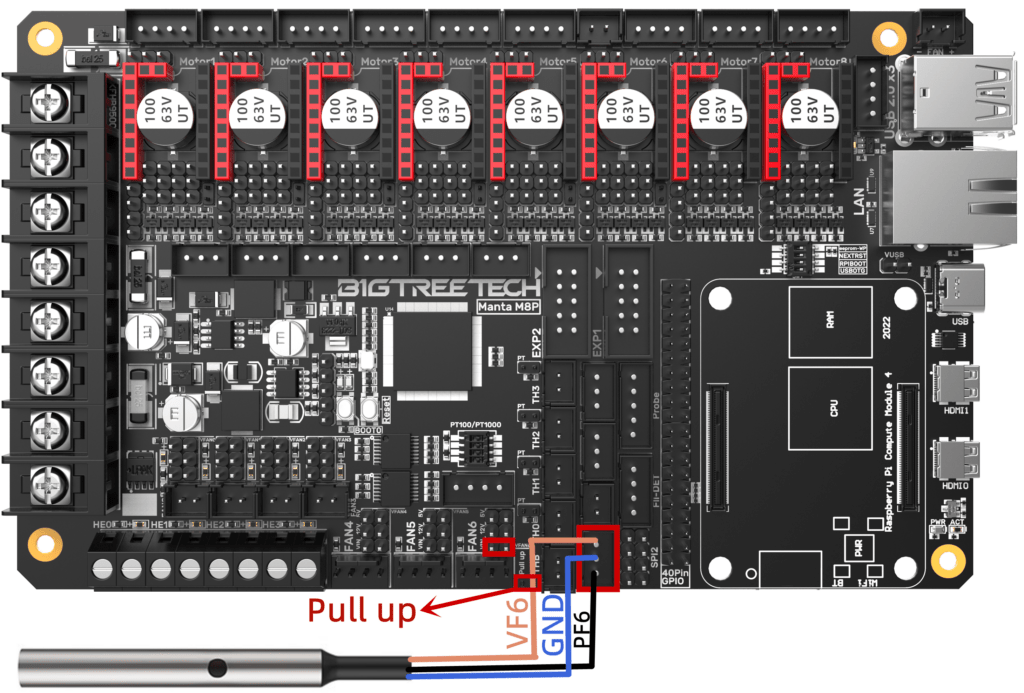
In the case that we use a mechanical sensor type Bltouch:
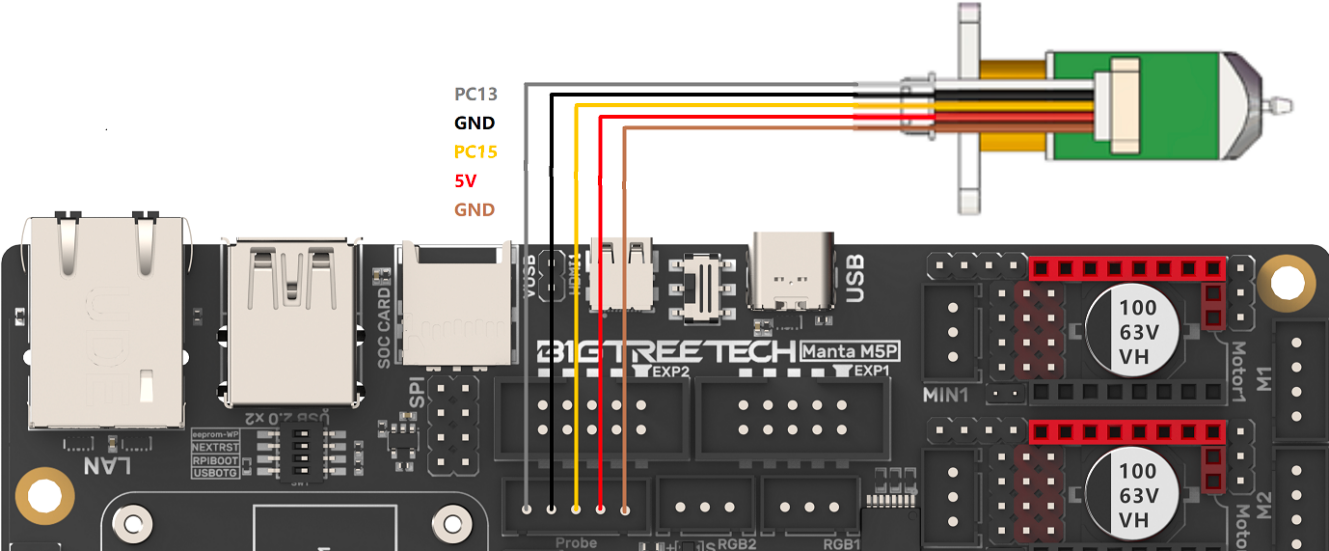
In the case that we use a proximity sensor, we have a jumper to select power and one to indicate if the sensor needs Pull-Up:
- NPN (always on) we will connect it in the following way, it is important to check the power jumper (in the example at 24v):
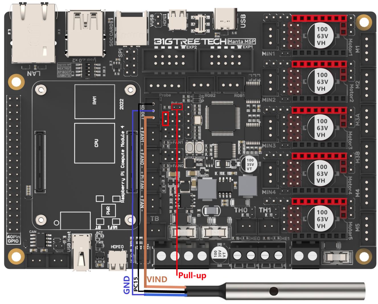
- PNP (always off) we will connect it following the following scheme, it is important to check the power jumper (in the example at 24v) and to place the Pull-Up jumper:
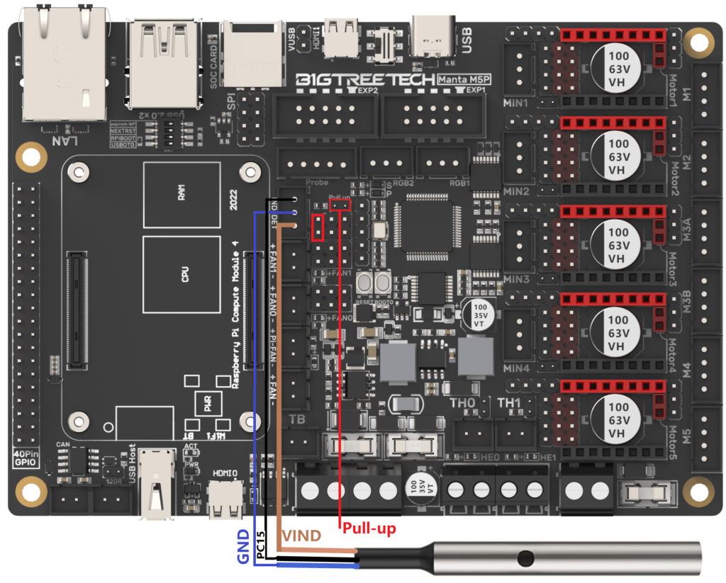
In the case that we use a mechanical sensor type Bltouch:

In the case that we use a mechanical sensor type Bltouch:

Filament Sensor
Filament sensors are a great addition to our printer as they will allow us to detect if we have a lack or problem with the filament and we will be able to stop and recover a print.
Normally, these filament sensors act as a simple switch that we can place on any pin that makes or can act as an enstop or limit switch. There are also more advanced filament sensors that require special configurations, which you can see in our filament sensor guides (Klipper/Marlin) for more information.
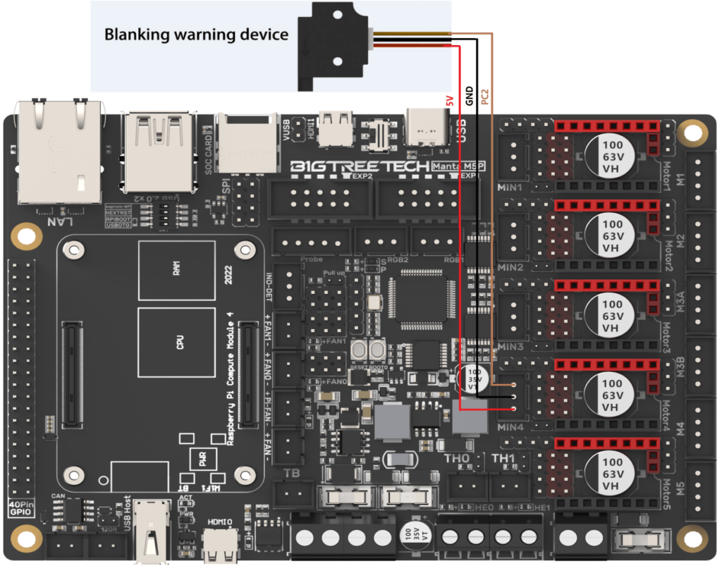
Installation is usually quite simple in the case of simple filament sensors:
Accelerometers
Another type of sensor that has become hugely popular with the growth of Klipper is accelerometers.
These sensors allow a series of tests to detect vibration patterns that your printer’s firmware then uses to compensate for those vibrations, a function called Input Shaper.
You can install an accelerometer directly to your M8P as follows:
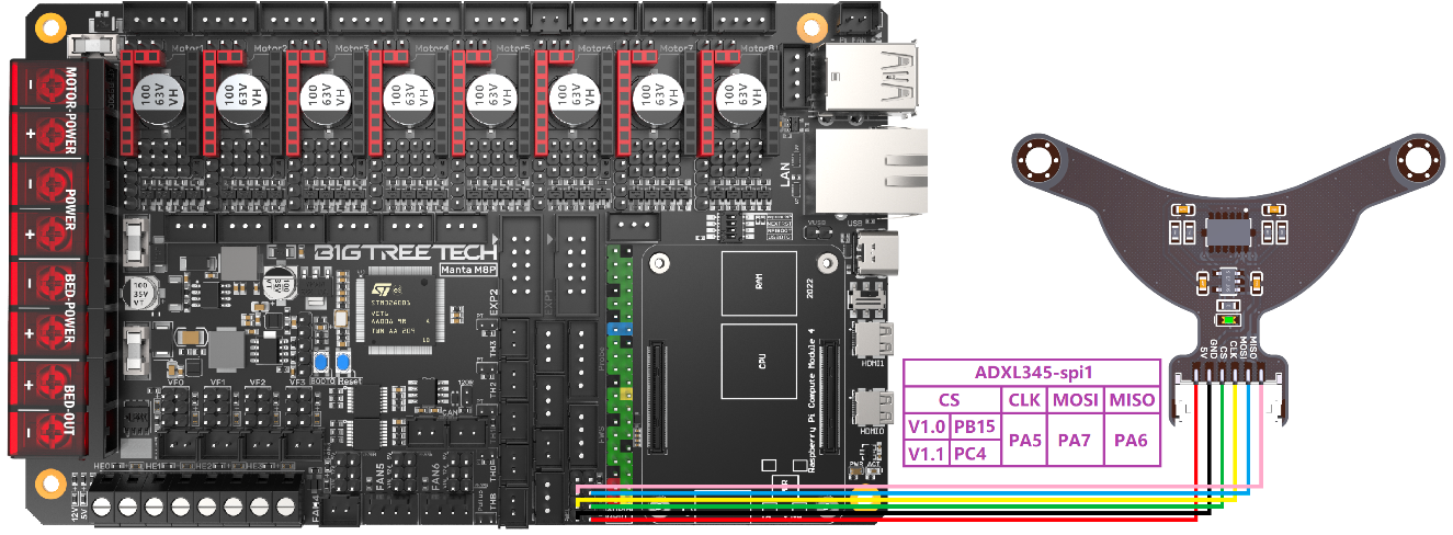
[adxl345]
cs_pin: PC4 # PB15 for V1.0
spi_bus: spi1
#spi_software_sclk_pin: PA5
#spi_software_mosi_pin: PA7
#spi_software_miso_pin: PA6
You can install an accelerometer directly to your M4P as follows:
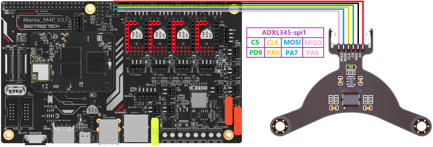
[adxl345]
cs_pin: PD9
spi_bus: spi1
#spi_software_sclk_pin: PA5
#spi_software_mosi_pin: PA7
#spi_software_miso_pin: PA6
You can install an accelerometer directly to your E3 EZ as follows:

[adxl345]
cs_pin: PC15
spi_bus: spi1
#spi_software_sclk_pin: PC10
#spi_software_mosi_pin: PC12
#spi_software_miso_pin: PC11
Displays
The Manta series has also taken special care in this aspect, providing connectivity for different types of screens.
LCD Screens
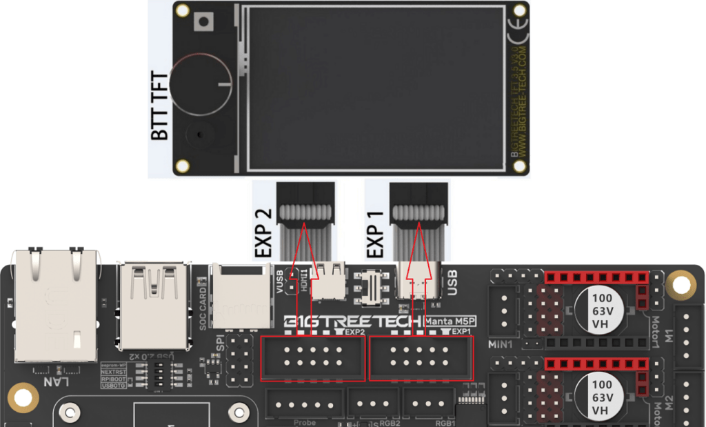
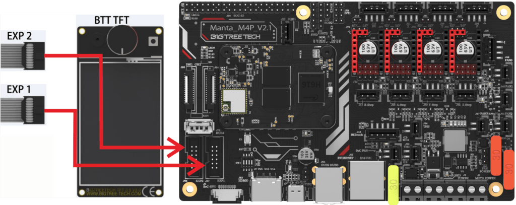
LCD screens are those that usually use EXP connectors and are normally managed by the printer’s firmware, displaying text menus to manage the different options.
The M8P supports a wide range of LCD displays with two EXP connectors:
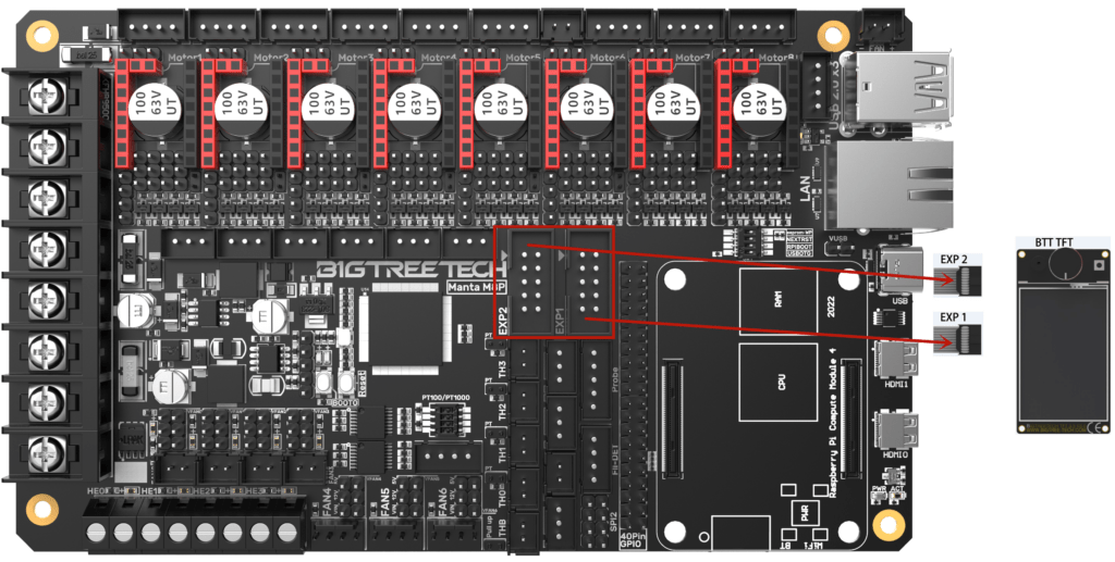
The M5P supports a wide range of LCD displays with two EXP connectors:
The M4P supports a wide range of LCD displays with two EXP connectors:
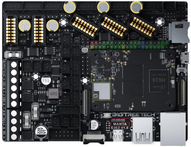
In the case of the E3EZ we have a single EXP connector, of the EXP3 type that is used in Creality printers, and that in a single connector has all the wiring for all the functions of this type of screen.

TFT Screens
In this type of display, they are normally connected using a serial connection using the TFT connector that all models incorporate. These screens, usually touchscreens, have their firmware that we can update to add improvements to the firmware.
In this aspect, Bigtreetech has one of the best dual TFT/LCD screens, so we advise you to use these in that firmware that supports both types of screen. In this regard, remember that Klipper does not support this type of serial screen connected to electronics currently, or at least not officially
DSI/SPI Displays
These screens normally interact with the host, CB1/CM4, displaying its interface… usually, KlipperScreen in the case of Klipper or Octodash in the case of Octoprint if we use Marlin. In both cases, the installation/configuration of these functionalities must be required in the system.
In this case, the M8P has a DSI connector for displays and a CSI connector for cameras of this type:
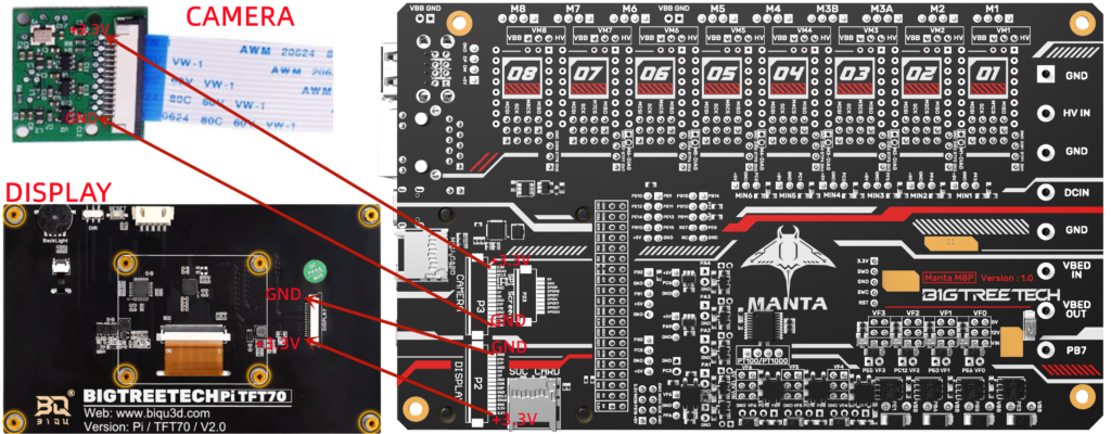
In the case of DSI, if we use CM4 as a host whose default interface is HDMI, we will need to unload the DSI1 driver using the following command from SSH:
sudo wget https://datasheets.raspberrypi.com/cmio/dt-blob-disp1-cam1.bin -O /boot/dt-blob.bin
Once the change is applied we will restart our host and we should have an image on our DSI screen. If you want to use HDMI again, all you have to do is remove //boot/dt-blob.bin from your system and the HDMI output will work as it did before.
In this case, the M5P has a DSI connector for displays and a CSI connector for cameras of this type:

In the case of DSI, if we use CM4 as a host whose default interface is HDMI, we will need to unload the DSI1 driver using the following command from SSH:
sudo wget https://datasheets.raspberrypi.com/cmio/dt-blob-disp1-cam1.bin -O /boot/dt-blob.bin
Once the change is applied we will restart our host and we should have an image on our DSI screen. If you want to use HDMI again, all you have to do is remove //boot/dt-blob.bin from your system and the HDMI output will work as it did before.
In this case, the M4P has a DSI connector for displays and a CSI connector for cameras of this type:
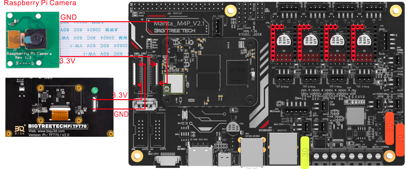
In the case of DSI, if we use CM4 as a host whose default interface is HDMI, we will need to unload the DSI1 driver using the following command from SSH:
sudo wget https://datasheets.raspberrypi.com/cmio/dt-blob-disp1-cam1.bin -O /boot/dt-blob.bin
Once the change is applied we will restart our host and we should have an image on our DSI screen. If you want to use HDMI again, all you have to do is remove //boot/dt-blob.bin from your system and the HDMI output will work as it did before.
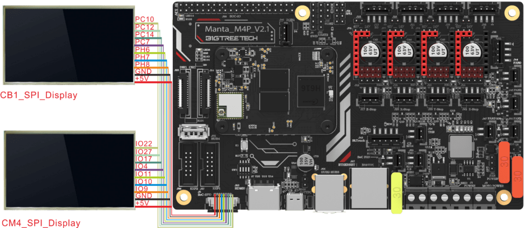
We also have support for SPI displays:
In this case, the E3 EZ has a DSI connector for displays and a CSI connector for cameras of this type:
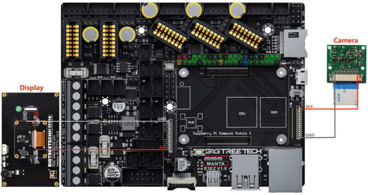
In the case of DSI, if we use CM4 as a host whose default interface is HDMI, we will need to unload the DSI1 driver using the following command from SSH:
sudo wget https://datasheets.raspberrypi.com/cmio/dt-blob-disp1-cam1.bin -O /boot/dt-blob.bin
Once the change is applied we will restart our host and we should have an image on our DSI screen. If you want to use HDMI again, all you have to do is remove //boot/dt-blob.bin from your system and the HDMI output will work as it did before.
Neopixel LED strips
Although they will not give us any advantage in print quality, LED strips allow us to add smart lighting functionalities either to illuminate the printing area, use them as a visual notification before events, or any other use that is useful to us.
The connection of an LED strip is very simple since Bigtreetech has direct support for them facilitating the task as you can see in the following diagrams, in any case, we advise you to check our neopixel guides for Klipper and Marlin:
On the M8P we have two connections dedicated to the management of neopixel LED strips:

On the M5P we have two connections dedicated to the management of neopixel LED strips:
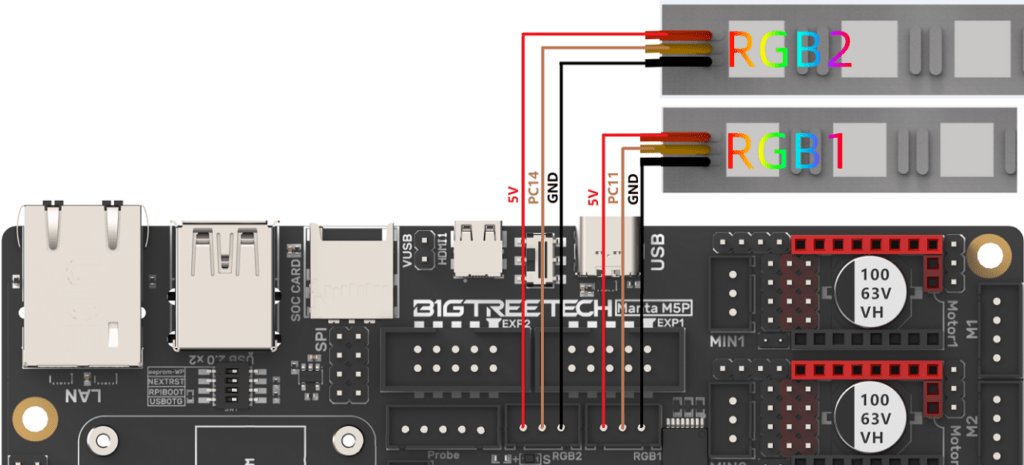
On the M4P we have two connections dedicated to the management of neopixel LED strips:

On the E3 EZ we have a connection dedicated to the management of neopixel LED strips:

Firmware
Klipper
Bigtreetech has always been very attentive to users, which is why it is one of the few brands that support projects related to Klipper, which ensures a better experience in its use.
That is why, depending on the CM4 module we use, we will have different options for Klipper distributions to install:Next we will proceed to install the Klipper system in our CB1 module, we have two options:
We will then proceed to install the Klipper system in our CB1 module, we have two options:
- Use the generic distribution of Bigtreetech, you can download it from here.
- Using RatOS you have some advantages, and disadvantages depending on your level of Klipper knowledge, such as the pre-installation of various components, compatibility with various electronics and printers with pre-configured and default macros. You can download it from here.
Once we have our image:
- Once you’ve downloaded the Klipper distribution you like the most, you’ll use Raspberry Pi Imager or balenaEtcherto transfer the Klipper image to your SD card. A card of at least 16-32Gb is advisable. For this guide, we’ll use RatOS, which is the Klipper distribution we usually use.


- Once the process is finished and from our computer’s explorer we will access our SD where we will have a partition called BOOT.
- The WiFi configuration, in case you don’t use your CB1 with a network cable, we will return to our system.cfg file where we will adjust our WIFI_SSID and WIFI_PASSWD:

- Next, we’re going to configure the specific options for our CB1, which in this case we’ll do on our BoardEnv.txt file, where we’ll adjust the following:
console=display– With this configuration theUART0port of the CB1 will be used as the console port for the use of serial clients such as MobaXeterm for debugging. If we want to useUART0to control our electronics from Klipper, we must setconsole=serialand Klipper can use //dev/ttsyS0as a serial ID to connect with our electronicsextraargs=video: normally our CB1 will detect the resolution of a screen connected by HDMI, in the cases that this does not work correctly we can specify the resolution using: extraargs=video=HDMI-A-1:1024×600-24@60 example for a BTT-HDMI7 (1024×600)extraargs=video=HDMI-A-1:800x480-24@60example for a BTT-HDMI5 (extraargs=video=HDMI-A-1:1024x600-24@60)overlays=tft35_spioverlays=mcp2515: in case we want to enable support for CANbus over SPI
IMPORTANT!!! the use of CANbus and the SPI port of the CB1 cannot be used simultaneously on the same bus without multiplexing.
SPI1_CLK=PH6
SPI1_MISO=PH8
SPI1_MOSI=PH7
TFT35_SPI_CS=PC7
MCP2515_CS=PC11
MCP2515_IRQ=PC9
CM4 modules typically come in two storage formats, using traditional SD or using built-in eMMC storage. In the following image you have the different versions and how to identify them:

We will then proceed to install the Klipper system on our CM4 module with SD, we have two options:
- Use the generic distribution of MainsailOS from the following link
- Using RatOS you have some advantages, and disadvantages depending on your level of Klipper knowledge, such as the pre-installation of various components, compatibility with various electronics and printers with pre-configured and default macros. You can download it from here.
Once you’ve downloaded the Klipper distribution you like the most…
- We will use Raspberry Pi Imager or balenaEtcherto transfer the Klipper image to our SD card. A card of at least 16-32Gb is advisable. For this guide, we’ll use RatOS, which is the Klipper distribution we usually use.
- During the process, before installing the image on our SD we can see an icon at the bottom right from which we can access the pre-configuration of some options, of which we advise you only to adjust:
- hostname: will be the display name or access name from our network instead of the IP, by default raspberrypi.local
- wireless: we can leave pre-configured our WiFi access data, SSID or the identifier/name of our network and the access password
- ssh, it is advisable to enable it, although normally the images we have suggested already have it

- We will follow the process:


In the case that we have a CM4 module with eMMC storage, it is slightly different since we will first have to “mount” this storage on our computer so that Raspberry Pi Imager or balenaEtcher have access to it to install the system image.
- The first step will be to install the
rpibootutility (available for Windows and Linux/MacOS) - We will activate in our electronics the USB OTG mode (normally switch 4) and BOOT (switch 3) to enter the BOOT mode, the way to enter this is usually through the microswitches that we can find near the module. By way of example:


- Once we have the microswitches in BOOT mode, we will connect the electronics to our computer with the USB-C cable (it is usually advisable that it is also powered by the printer’s power supply since some computers may not supply the necessary power for the CM4/electronics to work properly) and we will launch the
rpibootutility. - If everything has gone correctly, our computer will detect our CM4 as a storage unit and we can follow the previous process to copy the image from Raspberry Pi Imager or balenaEtcher .
The next step will be to access the web interface or install the components from Kiauh, we are not going to go into much detail since you have a guide of first steps with Klipper where you will find more information and details.
The next important step will be the creation and application of the Klipper firmware to our electronics:
To be able to use Klipper on our M8P v2.x we first need to create, apply the Klipper firmware to it and get the serial ID to include in our Klipper configuration (printer.cfg).
- We will connect to our host (CB1/CM4) using an SSH client (Putty, Terminals, MobaXterm, etc…) and launch the following commands:
 cd ~/klipper
 make clean
 make menuconfig
- A menu will appear to select the options that our Klipper firmware will have, in the case of the M8P we will leave it as we see in the following image:

- Once the options are selected, press the
Qkey to exit the menu andYesto save the settings.
To be able to use Klipper on our M8P v1.x we first need to create, apply the Klipper firmware to it and get the serial ID to include in our Klipper configuration (printer.cfg).
- We will connect to our host (CB1/CM4) using an SSH client (Putty, Terminals, MobaXterm, etc…) and launch the following commands:
 cd ~/klipper
 make clean
 make menuconfig
- A menu will appear to select the options that our Klipper firmware will have, in the case of the M8P we will leave it as we see in the following image:

- Once the options are selected, press the
Qkey to exit the menu andYesto save the settings.
To be able to use Klipper on our M5P we first need to create, apply the Klipper firmware to it and get the serial ID to include in our Klipper configuration (printer.cfg).
- We will connect to our host (CB1/CM4) using an SSH client (Putty, Terminals, MobaXterm, etc…) and launch the following commands:
 cd ~/klipper
 make clean
 make menuconfig
- A menu will appear to select the options that our Klipper firmware will have, in the case of the M5P we will leave it as we see in the following image:

- Once the options are selected, press the
Qkey to exit the menu andYesto save the settings.
To be able to use Klipper on our M4P we first need to create, apply the Klipper firmware to it and get the serial ID to include in our Klipper configuration (printer.cfg).
- We will connect to our host (CB1/CM4) using an SSH client (Putty, Terminals, MobaXterm, etc…) and launch the following commands:
 cd ~/klipper
 make clean
 make menuconfig
- A menu will appear to select the options that our Klipper firmware will have, in the case of the M4P we will leave it as we see in the following image:

- Once the options are selected, press the
Qkey to exit the menu andYesto save the settings.
To be able to use Klipper on our E3 EZ we first need to create, apply the Klipper firmware to it and get the serial ID to include in our Klipper configuration (printer.cfg).
- We will connect to our host (CB1/CM4) using an SSH client (Putty, Terminals, MobaXterm, etc…) and launch the following commands:
 cd ~/klipper
 make clean
 make menuconfig
- A menu will appear to select the options that our Klipper firmware will have, in the case of the E3 EZ we will leave it as we see in the following image:

- Once the options are selected, press the
Qkey to exit the menu andYesto save the settings.
- Next, we’ll launch the make command to compile the firmware. The compiled firmware will be created in the
out/klipper.binfolder which we advise you to transfer to your computer with the file transfer tools included in the SSH client programs themselves or an SFTP client.

- Once on our computer, we will rename the file
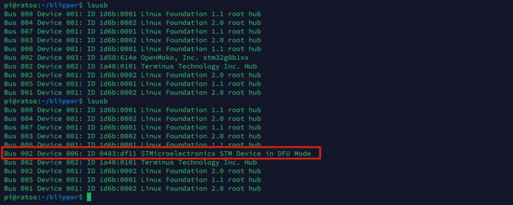
klipper.bin firmware.binand copy it to the root of an SD, ideally >2GB with FAT32/4096 format since the bootloader usually has limited compatibility. Once thefirmware.binhas been copied, we will safely remove the SD card and place it in our M8P (without power), we will power our M8P and in a few seconds, the firmware should have been applied. One of the ways to see if our firmware was applied correctly is to check the SD and check that the originalfirmware.binname changed tofirmware.CUR. - Once the Klipper firmware has been applied to our electronics, we will reconnect to our host via SSH and launch the following commands to obtain our serial ID used later in the
[mcu]section of ourprinter.cfgKlipper configuration file
ls /dev/serial/by-id/
If everything has gone correctly our Klipper will be able to connect with our Manta and follow the Klipper first step guide to continue with the rest of the configurations, in case we have problems we advise you to review/reapply the process or go to our Klipper troubleshooting guide where you can see possible causes and solutions to the most generic Klipper problems.
Marlin
Although these electronics are primarily intended for use with Klipper, they are supported by Marlin in their current versions.
As with Klipper, we are not going to go into detail describing how to compile our version of Marlin or how to configure its functionalities that we can find in our repository of guides for Marlin.
In the following table you will find the two most important values when compiling our Marlin, which is default_envs (in platformio.ini) and MOTHERBOARD (in /Marlin/Configuration.h):
| MARLIN | default_envs | MOTHERBOARD |
|---|---|---|
| M8P v2.0 | STM32H723ZE_btt | BOARD_BTT_MANTA_M8P_V2_0 |
| M8P v1.1 | STM32G0B1VE_btt | BOARD_BTT_MANTA_M8P_V1_1 |
| M8P v1.0 | STM32G0B1VE_btt | BOARD_BTT_MANTA_M8P_V1_0 |
| M5P v1.0 | STM32G0B1RE_manta_btt | BOARD_BTT_MANTA_M5P_V1_0 |
| M4P v2.1 | STM32G0B1RE_manta_btt | BOARD_BTT_MANTA_M4P_V2_1 |
| E3 EZ v1.0 | STM32G0B1RE_manta_btt | BOARD_BTT_MANTA_E3_EZ_V1_0 |
Where to buy the Bigtreetech Manta?
Here are some purchase links for the Bigtreetech Manta series:
| Bigtreetech Manta M8P | 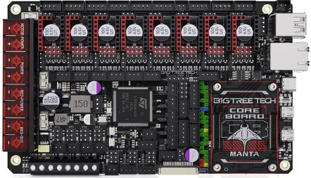 | ALIEXPRESS |
| Bigtreetech Manta M5P | 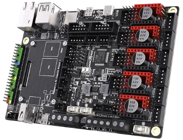 | ALIEXPRESS |
| Bigtreetech Manta M4P | 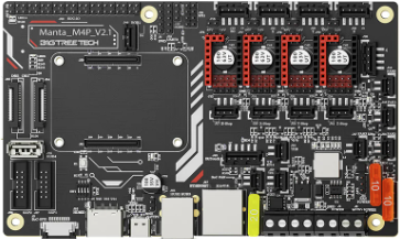 | ALIEXPRESS |
| Bigtreetech E3 EZ | 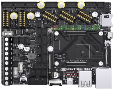 | ALIEXPRESS |
| Bigtreetech CB1 | 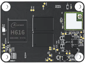 | ALIEXPRESS |






















Déjanos un comentario