A little over a week ago we were analyzing a powerful electronic board from the well-known manufacturer FYSTEC, specifically the FYSETC Spider. Feel free to visit it at the following link: Complete guide Fysetc Spider: A real «beast» for our 3D printers.
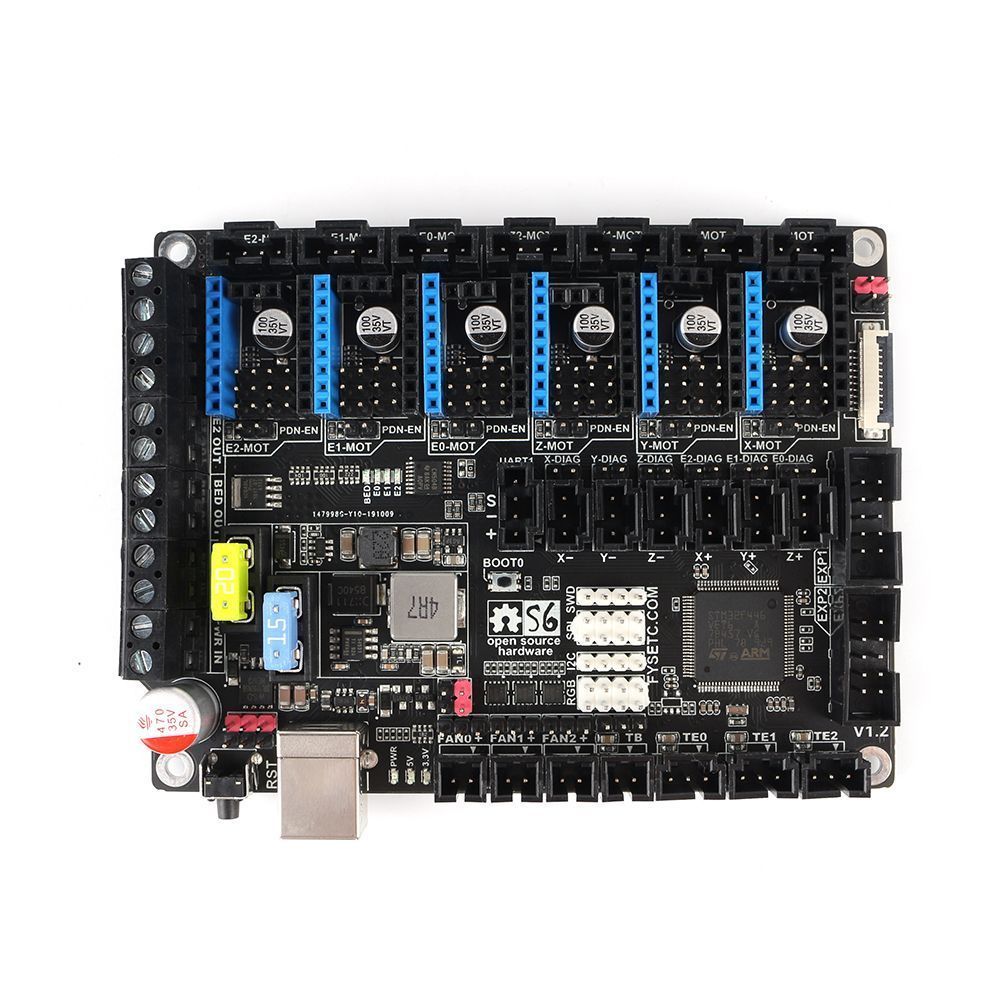
Today we bring you another detailed analysis of a smaller version of the electronic board FYSETC Spider, named FYSETC S6. Specially designed for small and medium format printers, but with all the power of its predecessor.
And all this in a contained board format that we can install on practically any machine, offering us incredible expansion and functionality options.
Before continuing I would like to remind you that we have a large community in Telegram. So if you want to support the project, join us or follow us on our social networks, we will be eternally grateful.
Brief introduction
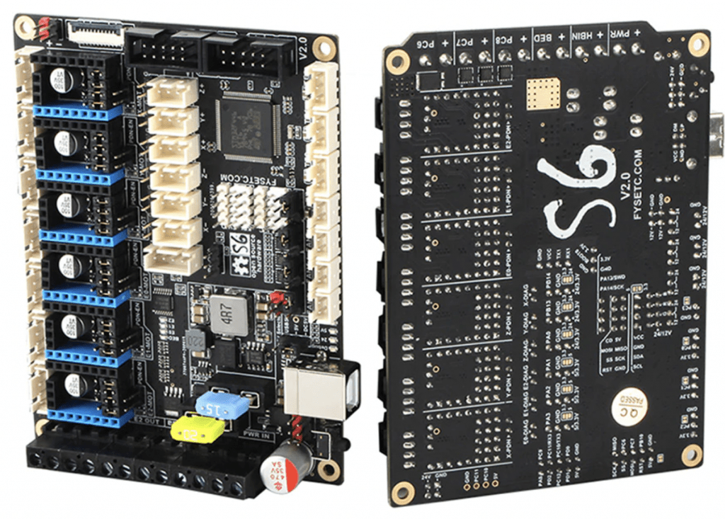
Once again, the component manufacturer FYSETC surprises us with another more than interesting electronics and breaks into the market to raise the bar in the development of controllers for 3D printing.
Among other features, our FYSETC S6 electronics has one of the most powerful MCUs on the market. Specifically, a STM32F446 32-bit driver. In this way you will not be left behind in power or use options of any current firmware.
I anticipate that it supports 6 driver sockets in an extremely compact format, maximum compatibility with the most important 3D printing firmwares and many other improvements that we will review below.
Where can I buy FYSETC S6 electronics?
As I always do, here are some direct links to Amazon and Aliexpress marketplaces for anyone interested in acquiring this electronic board, or any other of the components that we reference in this article.
If you use them, the price of the product will be the same as if you log in regularly, but 3DWork will have a small commission left. Something that will help us support the project and be able to offer you all these types of articles.
And as an alternative, you can also use our product finder for 3D printing, where with a single search you will be shown prices from different marketplaces (Amazon, Aliexpress, Banggood, etc.)
Diagrams of the FYSETC S6
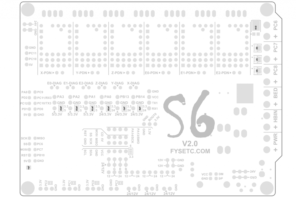
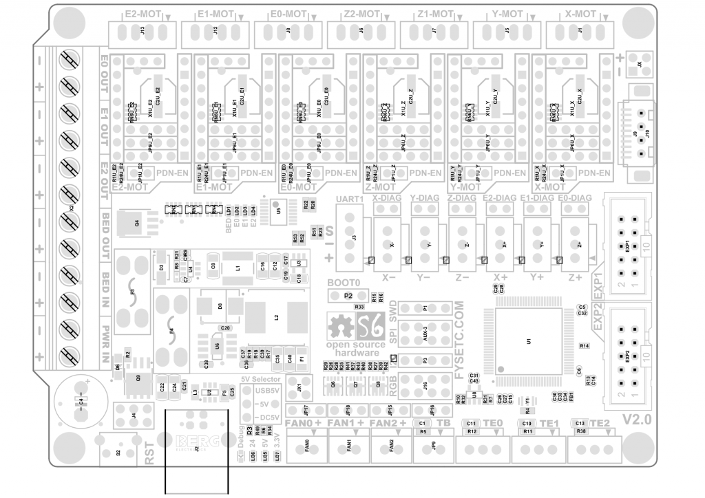
To get a better idea of this board, below we leave you some diagrams where you can quickly see the immense possibilities and potential of this electronics:
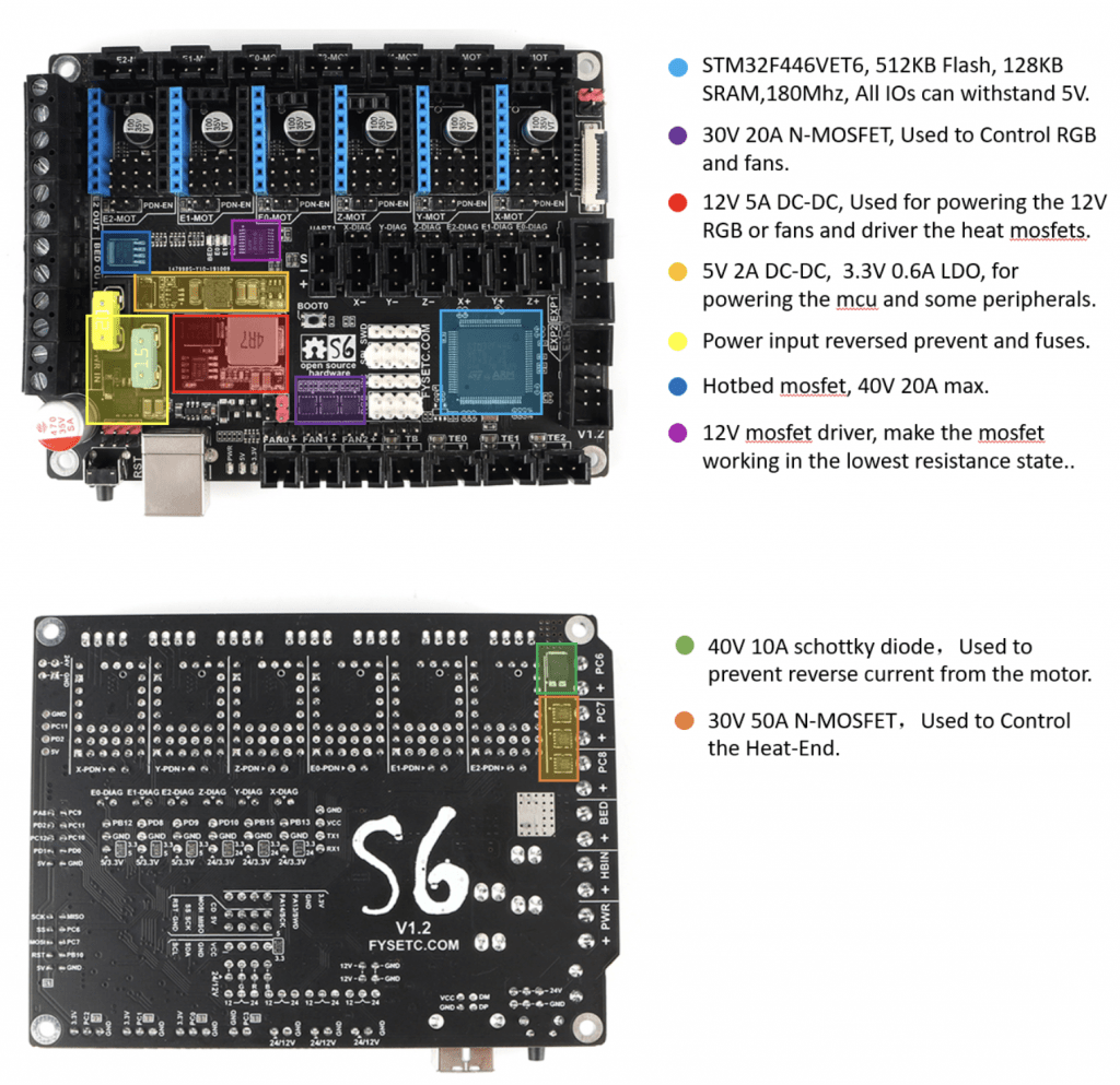
On the back of the plate we can find the definition of pins printed on it, something very useful to identify them.
Technical characteristics
In this short list you can find all the technical specifications of the FYSETC S6 electronics:
- Compact board size 117x87mm
- STM32F446 processor at 180Mhz
- 6 drivers with UART and SPI support (specific pins for TMC)
- Power 24V with converters to 12V / 5A, 5V / 8A (Raspberry, led strips, etc.)
- Protection with easy replacement fuses (protection of the main current input and hot bed)
- 10 PWM outputs controlled by MOSFET (1 heated bed, 3 Hotend, 3 fans, 3 RGB strips)
- 3 connectors for temperature sensors being able to use thermistors or thermocouplers (AD597 necessary)
- Up to 8 controllable fans (using only one extruder and without RGB LEDs), 2 RGB strips (12V or 24V) and 1 NeoPixel 5V strip
- UART connectors for connection and power supply of a Raspberry Pi (without external cables)
- 2 connectors for SD modules
- SD connector on the board and USB connector
- Pair EXP connectors to LCD / TFT or UART, I2C, CAN screens
- Bootloader to update firmware by SD or USB
FYSETC S6 main connections
Power supply selector (Jumper)
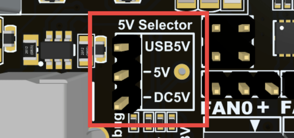
The FYSETC S6 electronics has a jumper to select the power to be used between USB or internal 5V adapter, which requires an external power supply. This jumper helps us avoid unpleasant problems when mixing different feeds.
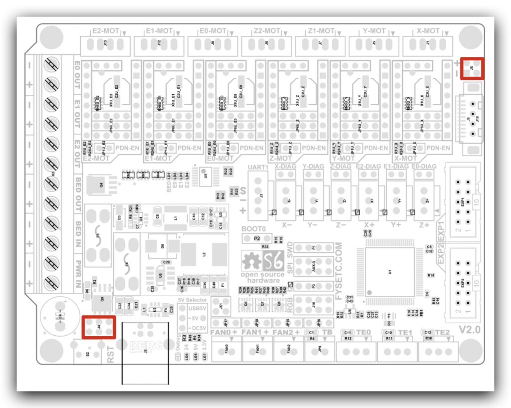
Power connectors

This board has a complete arsenal of connections and options, so the power supply part could not be less.
We have 3 exclusive output for extruders, 1 for the heatbed and with 2 current inputs, one general and one also for the heatbed, as you can see in the image above.
We also have other 24V power outputs for powering peripherals or other components, certainly a very complete board.
Endstop connectors
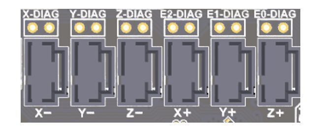
On this occasion we have the typical connectors for limit switches in the 3 axis. As is now customary in these electronics, FYSETC has implemented improvements in them to withstand different voltages.
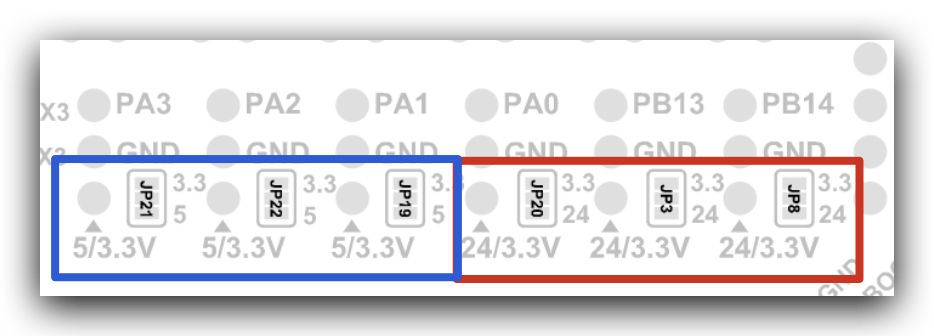
Some jumpers have been included (via solder bridge), so that we can initially determine the required voltage and deliver it to each connector independently (see image below).
So we have two connector blocks that can use two different types of voltages:
- X+/Y+/Z+ connectors, where we can choose between 5V or 3.3V (by default). Indicated for example for BLTouch / 3DTouch sensors of 5V.
- X-/Y-/Z- connectors, where we can choose between 24V or 3.3V (by default). These connectors are especially suitable for connecting inductive or capacitive leveling sensors.
Another important aspect about these types of connectors for limit switches is that we have several with ADC (purple point) and PWM (red point) functions. Very useful for the use of servos, LEDs or similar. In the following diagram we can see the type of each one:

BLTouch / 3DTouch Sensors
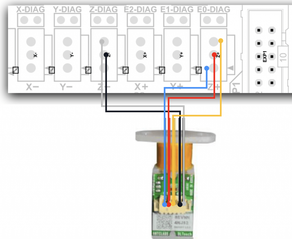
The installation of a leveling sensor of the type BLTouch / 3DTouch is very simple and we can do it using the following scheme (see the image above).
As always, we advise you to review our guide for more information on its installation and configuration. You can visit it at the following link: Install and configure BLTouch / 3DTouch in Marlin 2.0.x
Fans
The FYSETC S6 electronics have connections for 3 manageable fans, certainly a great improvement, as we mentioned in the characteristics of this board.
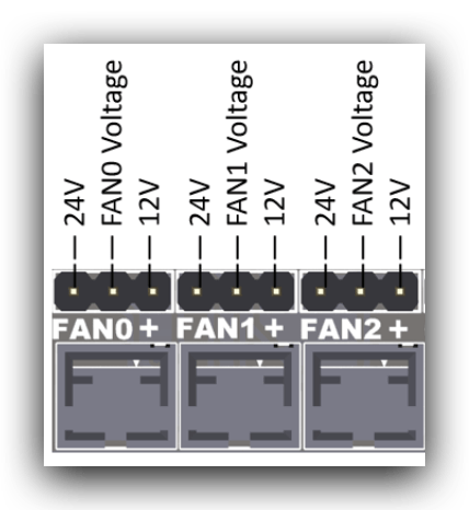
So we can, without the need for any power converter, configure the fan outputs so that they offer us 24V or 12V power, very practical if we need silent fans for our electronics or Hotend.
For this we must put the corresponding jumper between FAN0/1/2 Voltage and obviously, the voltage that we want to use at that moment.
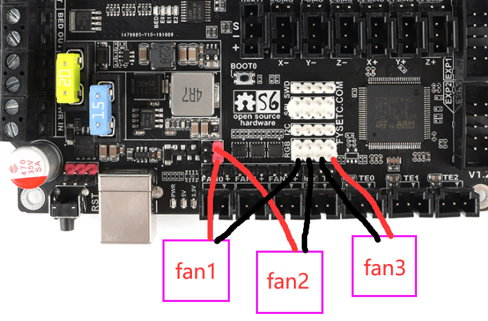
In the following diagram we can see it more easily. And in case we need more controllable fans, or to replace the current ones, we can always use the following pins in the case of not using RGB LEDs (click on images to enlarge)
Motor drivers
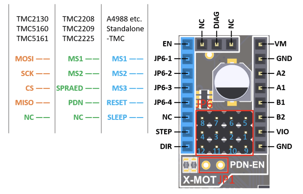
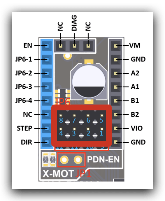
How could it be otherwise, all FYSETC S6 electronics have an extensive configuration of Jumpers/Pins (JP1 and JP6 in particular) to support a wide variety of drivers.
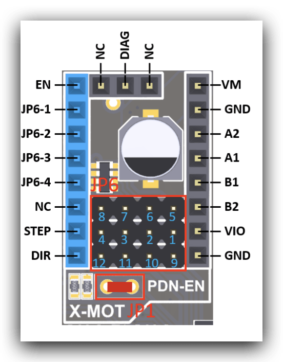
To use TMC2208/2225 or TMC2209/2226 drivers in UART (smart) mode, we will need to place a jumper on JP1. The rest of the configuration will be done directly in our firmware (microsteps, vref, mode, etc.)
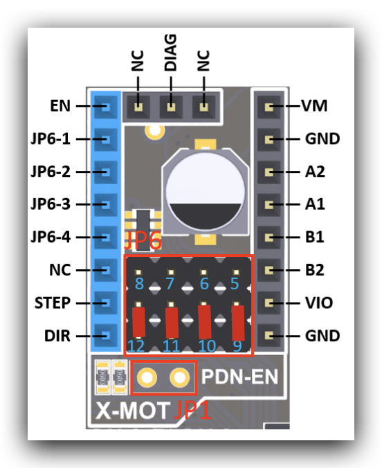
For TMC2130/5160/5161 drivers in SPI mode we need to place 4 jumpers in the JP6 connector (see image below).
To configure the drivers in STANDALONE (simple) mode we need to use the pins of the JP6 connector (1234-5678), in addition to the microsteps and some functionality in TMC drivers, as shown in the following diagram.
Sensorless / StallGuard
A very interesting feature for UART/SPI drivers that support it, is SensorLess. As you probably already know, sensorless allows you to use the motor itself as a limit switch.

This allows you to save components when assembling your printer, reduces possible mechanical failures of the same and avoids us using tedious wiring for the limit switches.
In the case of the Fysetc S6 we have some pins that by placing the corresponding jumper allow us to send the DIAG signal from the driver to the endstop. Remember that when activating this jumper we must have our firmware correctly configured.
LCD / Display Connectors
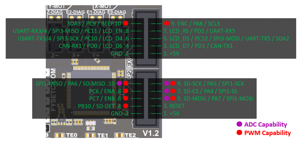
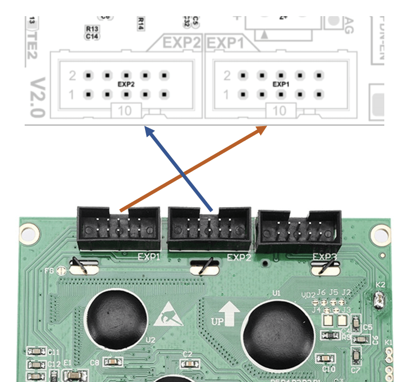
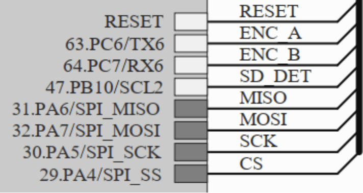
As expected, we have two EXP connectors compatible with the vast majority of displays of this type. In the following diagram we can see the available pin diagram and some available examples:
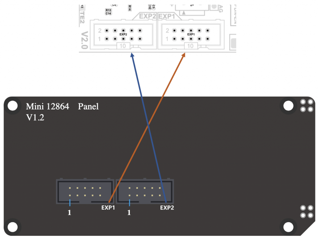
Small but functional screen for Marlin emulation mode, which with its LEDs gives a lot of play to customize your printer. In this case your connection couldn’t be simpler.
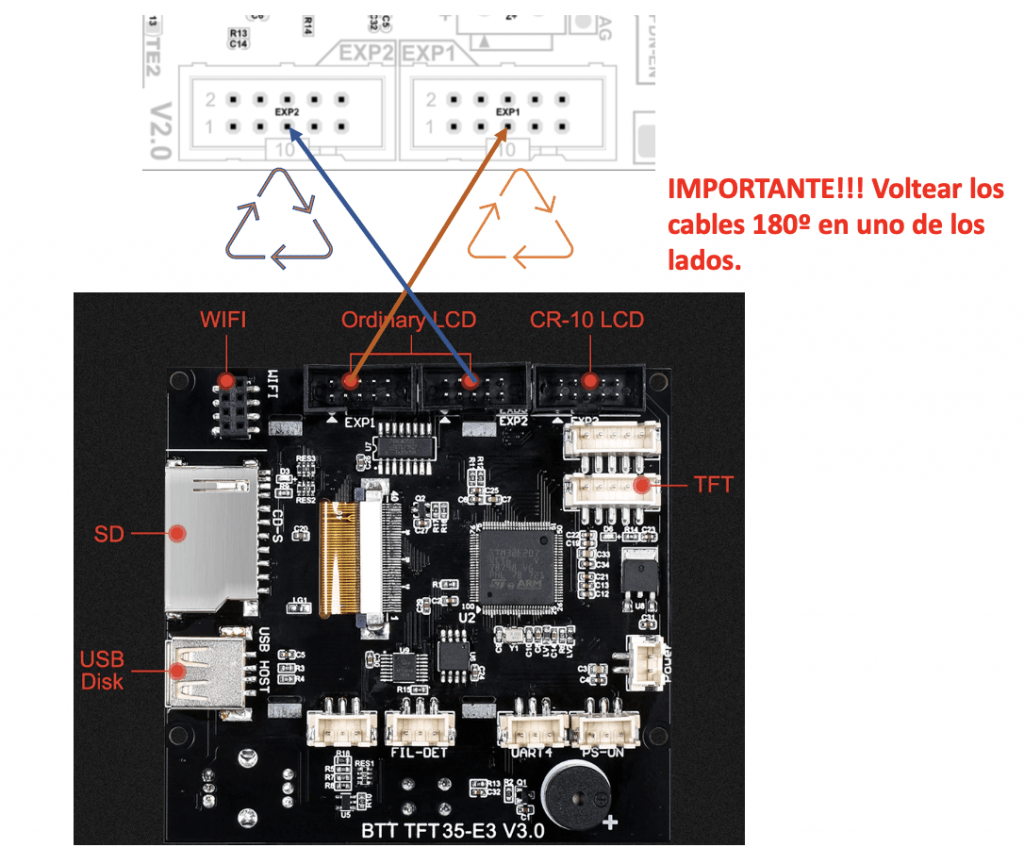
One of the most popular screens for its great dual mode where we can enjoy Marlin emulation and its advanced touch mode are the BTT TFT V3.0 screens.
CR10 Displays are used by many Creality printers and derivatives. They usually have 3 EXP connectors (EXP1/2/3) where one of them (EXP3) is a simplified type of connection of the other two, and is usually only found on Creality boards or similar.
In the case of our FYSETC we must use the EXP1 and EXP2 connectors connected directly to them on the board, without any complications.
USART / Serial Connectors
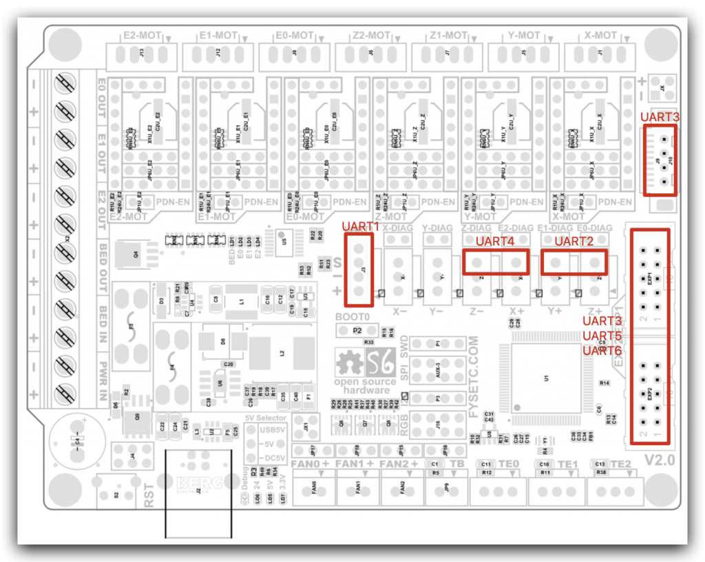
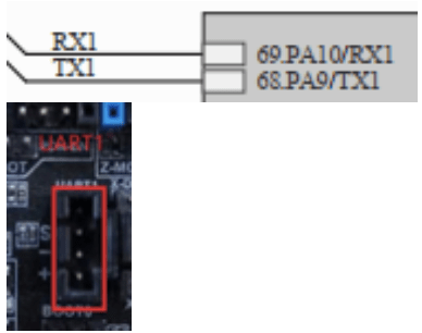
In all FYSETC S6 electronics we have up to 6 UART/Serial ports for the connection of serial devices such as TFT screens, WiFi modules, USB adapters for firmware update or similar.
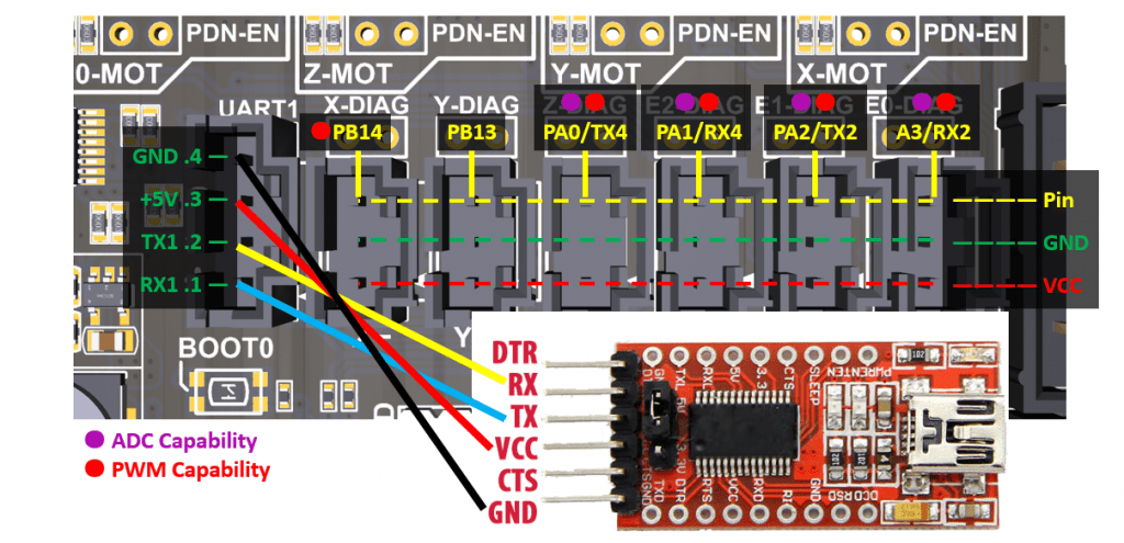
- USART1 -RX1 and TX1- (PA10 and PA9 in UART)
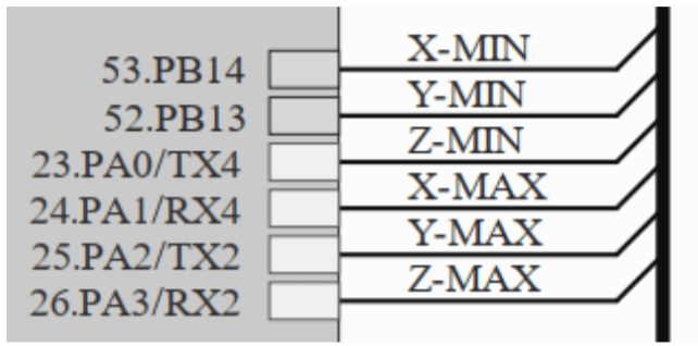
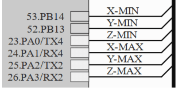
- USART2 -RX2 and TX2- (PA3 and PA2 in Z-MAX and Y-MAX)
- USART4 -RX4 and TX4- (PA1 and PA0 on X-MAX and Z-MIN)
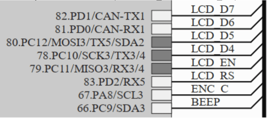
- USART5 -RX5 and TX5- (PD2 and SDA2 in EXP1)
- USART6 -RX6 and TX6- (PC7 and PC6 in EXP2)
To define these USART/Serial in Marlin, remember that as of Marlin 2.0.8 we can use up to 3 USART/Serial ports:
#define SERIAL_PORT -1  // 3DWORK USART USB
#define SERIAL_PORT_2 1 // 3DWORK USART1
#define SERIAL_PORT_3 3 // 3DWORK USART3 Example
You can have more detail in the following table:
Configuring Marlin
FYSETC S6 is compatible with the most important firmwares that currently exist for 3D printing. We leave you here the basic configuration for Marlin firmwares.
Modifying “Platformio.ini”

In this file you have to indicate the Chipset of your current electronics, so you should look at the beginning of the file for the value “env_default” and change it to the following:
default_envs = FYSETC_S6
One of the great options that this electronics has is that its bootloader allows you to update it using different methods. Either via SD on the LCD or external screen, since the board does not have SD or via USB by putting the board in BOOT0 mode.
By default the configuration of this board is prepared for this second option using DFU, which is not always comfortable having to access the board, change the pin and connect the USB cable.
So that the process does not fail if we do not do it that way and leave us the binary for its copy in the SD, we will proceed to comment on the following lines in the indicated file:
.../ini/stm32f4.ini

#
# FYSETC S6 (STM32F446RET6 ARM Cortex-M4)
#
[env:FYSETC_S6]
platform          = ${common_stm32.platform}
extends           = common_stm32
platform_packages = tool-stm32duino
board             = marlin_fysetc_s6
build_flags       = ${common_stm32.build_flags}
  -DVECT_TAB_OFFSET=0x10000
  -DHAL_PCD_MODULE_ENABLED
extra_scripts     = ${common.extra_scripts}
  pre:buildroot/share/PlatformIO/scripts/generic_create_variant.py
debug_tool        = stlink
# U1JO upload_protocol   = dfu
# U1JO upload_command    = dfu-util -a 0 -s 0x08010000:leave -D "$SOURCE"
Modifying “Configuration.h”

As always, we recommend adding a comment to any line that we modify. In this way it will be much easier to find our modifications later.
We will start by correctly configuring the SERIAL ports for this machine. Something essential for the proper functioning of our TFT, USB or WIFI connection.
#define SERIAL_PORT_2 -1 // 3DWORK FYSETC
BAUDRATE, helps us define the communication speed through the SERIAL port. The most common is to use 115200 or 250000 bds.
#define BAUDRATE 115200
Now we will define our MOTHERBOARD in the same way that we did in the file “platformio.ini”, this way we will indicate the type of chipset that our electronics has. This way Marlin will know which pin configuration to use at all times.
#define MOTHERBOARD BOARD_FYSETC_S6_V2_0 // 3DWORK FYSETC
We will define in this section the number of extruders and diameter of the filament that our printer uses. Normally our printers use 1.75mm diameter filament.
// This defines the number of extruders
// :[0, 1, 2, 3, 4, 5, 6, 7, 8]
#define EXTRUDERS 1

// Generally expected filament diameter (1.75, 2.85, 3.0, ...). Used for Volumetric, Filament Width Sensor, etc.
#define DEFAULT_NOMINAL_FILAMENT_DIA 1.75
Thermistors , in these constants we will indicate which thermistors our machine mounts. As always, it is advisable to identify them in advance, although the most normal thing is to select the value “1”.
It is very important to indicate the correct type of thermistor, otherwise the temperatures that Marlin will receive will not be correct.
To activate or deactivate the heated bed you must comment (or not) the thermistor of the same. This is how Marlin determines if he has a warm bed.
In our example and for this particular board, we use hotend and heatbed with a standard temperature sensor.
#define TEMP_SENSOR_0 1 // TE0
#define TEMP_SENSOR_1 0 // TE1
#define TEMP_SENSOR_2 0 // TE2
#define TEMP_SENSOR_3 0
#define TEMP_SENSOR_4 0
#define TEMP_SENSOR_5 0
#define TEMP_SENSOR_6 0
#define TEMP_SENSOR_7 0
#define TEMP_SENSOR_BED 1 // TB
#define TEMP_SENSOR_PROBE 0
#define TEMP_SENSOR_CHAMBER 0
#define TEMP_SENSOR_COOLER 0
PID, another important part in temperature management is the PID. Basically the PID is an algorithm that helps Marlin in his task of adequately controlling the temperature without having large fluctuations.
#define PIDTEMP // 3DWORK PID
#define PIDTEMPBED // 3DWORK PID
ENDSTOPS or limit switches, it is vital to verify when we change the electronics and turn on for the first time that the logic of the limit switches is correct. For this you can use the M119 command from a terminal like Pronterface.
OPEN would indicate that the limit switch is in the normal state (not pressed), and TRIGGERED when they are pressed. We can reverse this logic by changing these lines:
#define X_MIN_ENDSTOP_INVERTING false // Set to true to invert the logic of the endstop.
#define Y_MIN_ENDSTOP_INVERTING false // Set to true to invert the logic of the endstop.
#define Z_MIN_ENDSTOP_INVERTING false // Set to true to invert the logic of the endstop.
#define X_MAX_ENDSTOP_INVERTING false // Set to true to invert the logic of the endstop.
#define Y_MAX_ENDSTOP_INVERTING false // Set to true to invert the logic of the endstop.
#define Z_MAX_ENDSTOP_INVERTING false // Set to true to invert the logic of the endstop.
#define Z_MIN_PROBE_ENDSTOP_INVERTING false // Set to true to invert the logic of the probe.
Typically, machines will home in MIN (lower left corner) instead of MAX (upper right corner). If you want to invert the configuration you should modify the following:
#define USE_XMIN_PLUG
#define USE_YMIN_PLUG
#define USE_ZMIN_PLUG
//#define USE_XMAX_PLUG
//#define USE_YMAX_PLUG
//#define USE_ZMAX_PLUG
If you have TMC drivers in UART mode you can use, if the driver supports it, the use of SensorLess technology. This will allow you to dispense with physical limit switches, freeing your printer from extra components and cables.
Drivers, as we have already mentioned, this board has 6 sockets for drivers supporting different types of drivers and their configurations
In our example we use Drivers TMC2209 in UART mode (intelligent), with independent double Z axis and a single extruder:
#define X_DRIVER_TYPE  TMC2209 // 3DWORK DRIVERS
#define Y_DRIVER_TYPE  TMC2209 // 3DWORK DRIVERS
#define Z_DRIVER_TYPE  TMC2209 // 3DWORK DRIVERS
//#define X2_DRIVER_TYPE A4988
//#define Y2_DRIVER_TYPE A4988
#define Z2_DRIVER_TYPE TMC2209 // 3DWORK DRIVERS
//#define Z3_DRIVER_TYPE A4988
//#define Z4_DRIVER_TYPE A4988
#define E0_DRIVER_TYPE TMC2209 // 3DWORK DRIVERS
STEPS or motor steps, in this section we indicate to our Marlin firmware the motor steps necessary to perform movements.
#define DEFAULT_AXIS_STEPS_PER_UNIT { 80.00, 80.00, 400.00, 93 } // 3DWORK Ender3 X, Y, Z, Extruder
S_CURVE_ACCELERATION, this functionality offers an important improvement in print quality, since it will smooth the acceleration or deceleration of our printer when the header is in motion.
#define S_CURVE_ACCELERATION // 3DWORK
PROBE or leveling sensor, as always I recommend reading the guide Configure BLTouch to ensure that prints always have as perfect a first layer as possible.
We will start by indicating where our leveling sensor is connected, in this case we will connect it to the Z- limit switch connector.
#define Z_MIN_PROBE_USES_Z_MIN_ENDSTOP_PIN // 3DWORK PROBE on Z-MIN
Sensor type BLTouch or Inductive, there are different types of sensors. Depending on the used we will have to uncomment one or the other.
In the case of an Inductive sensor:
#define FIX_MOUNTED_PROBE // 3DWORK PROBE
In the case of a BLTouch type sensor:
#define BLTOUCH // 3DWORK PROBE
Sensor offsets, it is extremely important to tell Marlin where our leveling sensor is installed. For this we will define the PROBE OFFSETs.
The Offset is the distance between the tip of the nozzle and the tip of the leveling sensor, which depending on its location will be positive or negative values (X, Y and Z coordinates).
In our case, our sensor is displaced to the left of the nozzle in X 30mm and 10mm in Y towards the bottom of the printer.
#define NOZZLE_TO_PROBE_OFFSET { -30, 10, 0 } // 3DWORK PROBE
PROBING_MARGIN (in previous versions MIN_PROBE_EDGE), it is very normal that we have a glass as a printing base in our printers, although personally we like more magnetic PEI sheets.
They are somewhat more susceptible to being marked with blows, but they have excellent adhesion, they do not limit the size of the bed and removing the pieces is extremely simple and fast.
In any case, we already have glass or another surface, it is advisable that the sensor is away from any object that may bother it during the leveling process, such as staples to fix the glass or the mismatch of the beginning and end of the bed that makes the sensor unable to measure.
For this we will use PROBING_MARGIN, and we will indicate how many millimeters to move away from the edges of the bed. In our case using a leveling sensor BLTouch and a PEI platform.
#define PROBING_MARGIN 10 // 3DWORK PROBE
Direction of motors, another common problem when starting a printer is that the wiring of the coils of our motors is incorrect. Because of this, two things can happen:
- That the coil connectors are mixed. It is easy to identify as the motor will not turn properly and will jerk. To solve it you must check the pinout of the old board and/or the motor, compare it with that of our new board and adapt it.
- That our motor rotates in the wrong direction. In this case again we have two options. The first and advisable one is to modify the motor rotation in Marlin and the second is to reverse the wiring of one of the motor coils.
In our case, we opt for the first one by modifying the following lines in Marlin, changing the current value to the contrary. In this case we invert the Z axis.
#define INVERT_X_DIR true
#define INVERT_Y_DIR true
#define INVERT_Z_DIR false // 3DWORK We reverse the rotation of the Z axis
Print size, if we have used a generic Marlin it is important to verify that the print dimensions are correct for our machine, since we will have the default dimensions configured.
In this example we use an Ender 3 at its maximum size. As always, it is advisable to verify that you can physically reach these measurements and adjust it if necessary:
#define X_BED_SIZE 235 // 3DWORK BED
#define Y_BED_SIZE 235 // 3DWORK BED
And we will also define the size of our Z axis (maximum offset height):
#define Z_MAX_POS 250 // 3DWORK BED
Filament sensor, we recommend you to check our guide of installation and configuration of a filament sensor. Yo can find the article in this link.
#define FILAMENT_RUNOUT_SENSOR // 3DWORK Filament sensor
As with the limit switches, it is advisable to check the status of the filament sensor with an M119 command, which will appear as TRIGGERED (if it has filament) and OPEN (without it). In the case that it seems inverted, we must play with the value of (LOW/HIGH) in our Marlin by modifying the following lines:
#define FIL_RUNOUT_STATE LOW // 3DWORK Filament sensor
In the case that our filament sensor works by detection of filament flow (such as the BigTreeTech Smart Filament Sensor) we must enable the following:
#define FILAMENT_MOTION_SENSOR // 3DWORK Filament sensor
Self-leveling, in the /Leveling section of our bot @ThreeDWorkHelpBot you have more detailed information on how to activate UBL self-leveling (the most advanced and recommended for beds of a certain size or with problems) and MESH leveling, that allows to create a mesh without any sensor doing the process manually.
In any case, for this example we will enable the BILINEAR auto leveling option:
#define AUTO_BED_LEVELING_BILINEAR // 3DWORK PROBE
It is important to tell Marlin to also enable self-leveling (G29) after a homing (G28), although in current versions it is no longer necessary (but we prefer enabling it).
#define RESTORE_LEVELING_AFTER_G28 // 3DWORK PROBE
In the case of BILINEAR we will specify the number of points to be made per mesh in the next part of Marlin. By default Marlin performs 9 probes (3 x 3 = 9 probes).
if EITHER(AUTO_BED_LEVELING_LINEAR, AUTO_BED_LEVELING_BILINEAR)
// Set the number of grid points per dimension.
#define GRID_MAX_POINTS_X 3 // 3DWORK PROBE
Another function that we must enable for safety is the Homing in the center of the bed. This function allows us to ensure that the sensor has a surface to detect the limit switch and visually verify that our Offsets are correct.
#define Z_SAFE_HOMING // 3DWORK PROBE
EEPROM, in the EEPROM Marlin stores configuration values of different functions so that these can be used by the system and be modified by the user without the need to continually edit the Marlin source files, compile and upload the firmware at each change.
It is highly recommended to activate it, and with our Fysetc S6 we will not have any memory problems, as in very old or obsolete electronics:
#define EEPROM_SETTINGS // 3DWORK EEPROM
#define EEPROM_CHITCHAT // 3DWORK EEPROM
Nozzle Park, in this example we have added a filament sensor. For this to work we will activate NOZZLE_PARK_FEATURE, which basically allows us to “park” the print head in a safe area to carry out the filament changes.
However, even if we do not have a filament sensor, it is highly advisable to have it active, since it allows us to improve the pause functions.
#define NOZZLE_PARK_FEATURE // 3DWORK
SD, if we want our Marlin to be able to read from our SD, either the one on the board or on a screen that is compatible (note that the Touch is not), you must activate the SD support in our Marlin firmware:
#define SDSUPPORT // 3DWORK SD
Advanced Homing Menu, it is not necessary but it is highly advisable in the case of tests to enable this function that allows us to perform a separate homing of each axis.
#define INDIVIDUAL_AXIS_HOMING_MENU // 3DWORK Improvements
Modifying “Configuration_adv.h”
Now we will proceed to modify the following file, the “Configuration_adv.h”, which usually has the most advanced configurations and options of our Marlin. So let’s get to it:
Scroll and long file names, it is interesting to activate this function to be able to show the full name of the files to be printed. Like the previous one and for it to work correctly we have to activate the following option:
#define LONG_FILENAME_HOST_SUPPORT // 3DWORK Improvements
#define SCROLL_LONG_FILENAMES // 3DWORK Improvements
SD connection, previously in the file “Configuration.h” we enabled the support for SD and in the “Configuration_adv.h” file we will define where Marlin will try to use that SD from.
We basically have three options. LCD where we will use the Marlin screen. ONBOARD where we will use the one on the board. And CUSTOM_CABLE where we will indicate that we use an external reader connected to the board.
As we mentioned previously, not all screens that have SD will work correctly. In our case we will use the one on the screen since the Fysetc S6 does not have an SD connector integrated into the board.
#define SDCARD_CONNECTION LCD // 3DWORK SD
Fans, a great success by Fysetc the inclusion of 3 manageable fans. In addition, we have the possibility of feeding them with different voltages from the board itself without the need for converters. And in particular, in our FYSETC S6 electronics we have 24V and 12V available.
The definition of the pin of each FAN can be found in “…/Marlin/src/pins/stm32f4/pins_FYSETC_S6.h“, which is used by Marlin as a common pins file for the S6 and the Spider.
FAN0, in this case we are not going to make any changes to its role since it is the layer fan and this is managed by the slicer itself to cool the filament.
FAN1, in our example we are going to assign it to the Hotend so that it is dynamically activated when it is in operation, avoiding possible wear of our fan and unnecessary noise:
#define E0_AUTO_FAN_PIN FAN1_PIN // 3DWORK FAN1 assigned to the hotend
...
#define EXTRUDER_AUTO_FAN_TEMPERATURE 50 // 3DWORK FAN1 activation by temperature
#define EXTRUDER_AUTO_FAN_SPEED 255   // 255 == full speed
FAN2, and if you wish, we can activate FAN2 as a dynamic electronics fan so that it is activated when the drivers are in use, again minimizing wear and noise from the fan.:
#define USE_CONTROLLER_FAN // 3DWORK FAN2 enabled electronic managed ventilation
...
#define CONTROLLER_FAN_PIN FAN2_PIN // 3DWORK FAN2 assigned to the electronic
...
#define CONTROLLER_FAN_EDITABLE // 3DWORK FAN2 manageable GCode M710
...
#define CONTROLLER_FAN_MENU  // 3DWORK FAN2 enable screen management menu
Babystepping, an almost essential function. Babystepping allows us to modify the height of Z in real time during a print. This allows us to manually adjust this height to our liking.
In our example we will enable that it can be activated with a double click on the button/encoder, which is always available, and show us graphic improvements in the adjustment to understand the direction of the adjustment from the screen.
#define BABYSTEPPING // 3DWORK Improvements
#define DOUBLECLICK_FOR_Z_BABYSTEPPING // 3DWORK Improvements
#define BABYSTEP_ALWAYS_AVAILABLE // 3DWORK Improvements
#define BABYSTEP_ZPROBE_GFX_OVERLAY // 3DWORK Improvements
Retries in case of failure in leveling, another very useful function is to be able to retry the homing process in case of failure. Sometimes our leveling sensor may have a specific failure and through this function it will allow us to try again a finite number of times.
#define G29_RETRY_AND_RECOVER // 3DWORK Improvements
#define G29_MAX_RETRIES 4 // 3DWORK Improvements
ARC support, offers us a substantial improvement in the quality of our prints. And also when we print through serial devices like TFT, Octoprint, etc.
It allows to simplify the GCodes commands by minimizing the number of movements and making them more fluid, avoiding a large number of retractions.
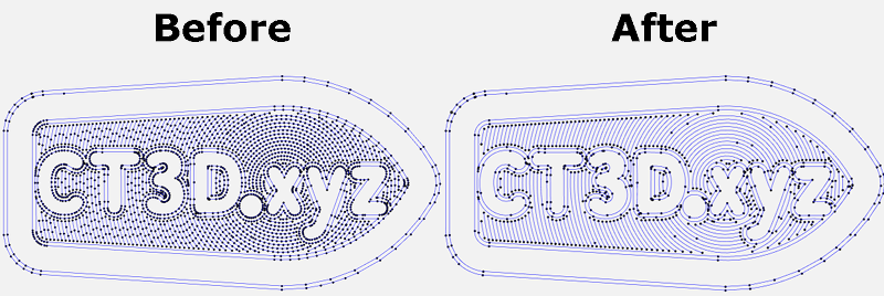
To use it we must configure our filleting (Slicer) to apply these changes or in the case of Octoprint we can use a Plugin. Regarding the changes in Marlin:
#define ARC_SUPPORT // 3DWORK Improvements
It is important to emphasize that in the case of enabling ARC for its use it is advisable, in the case that we also have it enabled, compatibility with S_CURVE.
Advanced pause, as we discussed earlier in this example we use a filament sensor. For it to work correctly we have to enable ADVANCED_PAUSE_FEATURE, which enables the GCode M600 command to change the filaments.
This can be done with or without a leveling sensor and requires NOZZLE PARK for its correct operation.
#define ADVANCED_PAUSE_FEATURE // 3DWORK
UART/SPI driver configuration, with our UART/SPI drivers we have to correctly configure the advanced parameters that we will find in the HAS_TRINAMIC_CONFIG section.
Microsteps, although we can configure from 16 to 256 microsteps, we do not advise you at all to use a value other than 16. With these microsteps, the definition that we could achieve mechanically is practically impossible to achieve with normal printers, in addition to the drivers TMC already performs the interpolation themselves to offer us maximum reliability and precision.
Reliability is another important aspect when it comes to microstepping. The stepper motors we use in our printers lose torque (and steps) at high revs. So increasing this definition of steps will exponentially increase the reliability percentage, and therefore our parts will not come out correctly.
In the following example we can see how we have 16 microsteps for our X axis.
#if AXIS_IS_TMC(X)
#define X_CURRENT 650 // (mA) RMS current
#define X_CURRENT_HOME X_CURRENT
#define X_MICROSTEPS 16 // 0..256
#define X_RSENSE 0.11
#define X_CHAIN_POS -1
#endif
Another important value of the previous values is that of CURRENT, where we will adjust the current of our motors. You can also adjust them from the LCD from Settings/Advanced/TMC along with other options that we will explain below.
STEALTHCHOP, it is important to enable it if we want our motors to be “silent” since if it will not be working in SpreadCycle mode, which is the power mode.
#define STEALTHCHOP_XY // 3DWORK DRIVERS
#define STEALTHCHOP_Z // 3DWORK DRIVERS
#define STEALTHCHOP_E // 3DWORK DRIVERS
Although rare, some extruders may work better with StealthChop mode disabled. If this is our case, we will comment on the following line.
//#define STEALTHCHOP_E // 3DWORK DRIVERS
CHOPPER TIMMING, is used by StealthChop for the synchronization of signals to the motors. This has to match the voltage used in our printer, in the case of Ender 3 and normally in all printers is 24V.
#define CHOPPER_TIMING CHOPPER_DEFAULT_24V // 3DWORK DRIVERS
Monitor Status, this function allows Marlin to control in detail all the parameters of the drivers to be able to adjust, for example, their temperature. This will help us avoid more serious problems.
#define MONITOR_DRIVER_STATUS // 3DWORK DRIVERS
Hybrid Threshold, another interesting function is Hybrid Threshold that allows Marlin to switch between StealthChop (silence) or SpreadCycle (power) dynamically based on the speed of our movements.
#define HYBRID_THRESHOLD // 3DWORK DRIVERS
#define X_HYBRID_THRESHOLD 100 // [mm/s]
#define Y_HYBRID_THRESHOLD 100
#define Z_HYBRID_THRESHOLD 15
In our case we use the values indicated for an Ender, which are 100mm/s for X Y and 15mm/s for Z, although we can always adjust it to our needs.
TMC Debug, in this case it is a requirement to enable MONITOR_DRIVER_STATUS that will allow us to have the M122 command accessible. Very useful for obtaining advanced information on the status and configuration of our drivers.
#define TMC_DEBUG // 3DWORK DRIVERS
The “pins_FYSETC_S6.h” file
Another important file is the pin configuration. In our electronics FYSETC we specifically have it at our disposal in the following route:
- …/Marlin/src/pins/stm32f4/pins_FYSETC_S6.h
Actually we should not carry out any type of operation at the moment, but we leave it here as a reference in case in the future someone needs its modification (or consultation).
Updating our firmware
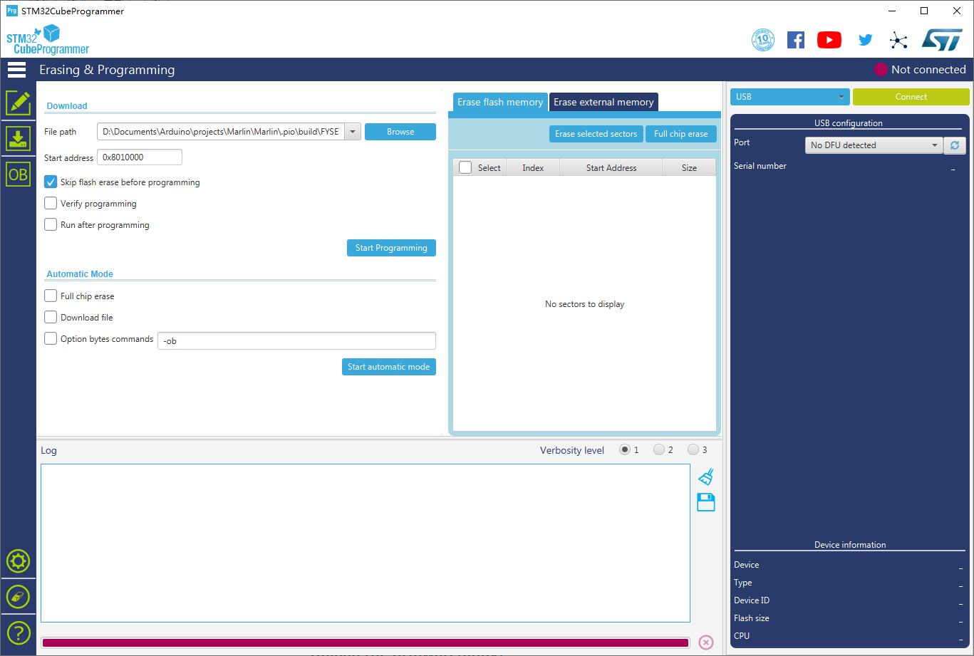
The FYSETC S6, like its sister the FYSETC Spider, has several options to easily update its firmware. We will list them below:
Using an SD Card
The simplest option is to use an SD for updating, which is the default method used by the board’s bootloader.
The process is very simple and we just have to copy our “firmware.bin” to the root of the SD formatted in FAT32, insert the SD in the module slot and wait about 30 seconds for the process to finish.
Once the file “firmware.bin” is finished, it should be renamed to “OLD.BIN”, which we can save as a backup (remember that a compiled firmware cannot be modified, this process can only be done with the source files of your firmware and recompiled).
Using DFU/USB mode (via cable)
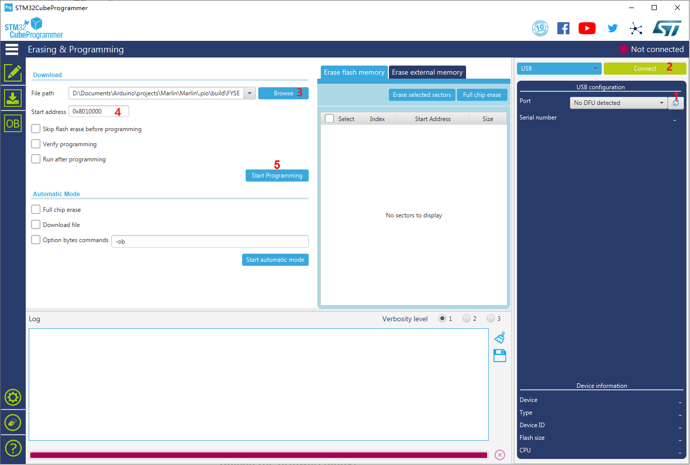
Another way to update our board, especially in the case of not having a module or LCD screen with SD, is using the DFU mode. The way to do it would be the following:
- Download STM32 Cube Programmer (Windows, Mac and Linux)
- Open the official flashing application
- We will put our Fysetc S6 board in DFU mode
- FYSETC S6 v1.2: With the board completely turned off, we will press and hold the BOOT0 button and with the button pressed we will connect the board to our computer using the USB cable. This operation will enter DFU mode. Once connected and in DFU mode, we will release the button.
- FYSETC S6 v2: With the board completely off we will put the connector jumper BOOT0 to 3.3v and we will connect the board to our computer using the USB cable. This will activate DFU mode in our electronics. Once the firmware update process is finished don’t forget to remove the BOOT0 jumper.
- Once in DFU mode we will return to the application and carry out the following steps:
- We will press the refresh button to detect the DFU port
- We will press the CONNECT
- button We will select the firmware.bin created
- In START ADDRESS we will put 0x8010000
- We will press START PROGRAMMING
And well, if we have followed the instructions in this regard and everything has worked correctly we should already have our new firmware uploaded to the FYSETC S6 electronics. I can only congratulate you on having reached this point.
LCD FYSETC MINI 12864 V2.1 (Neopixel)
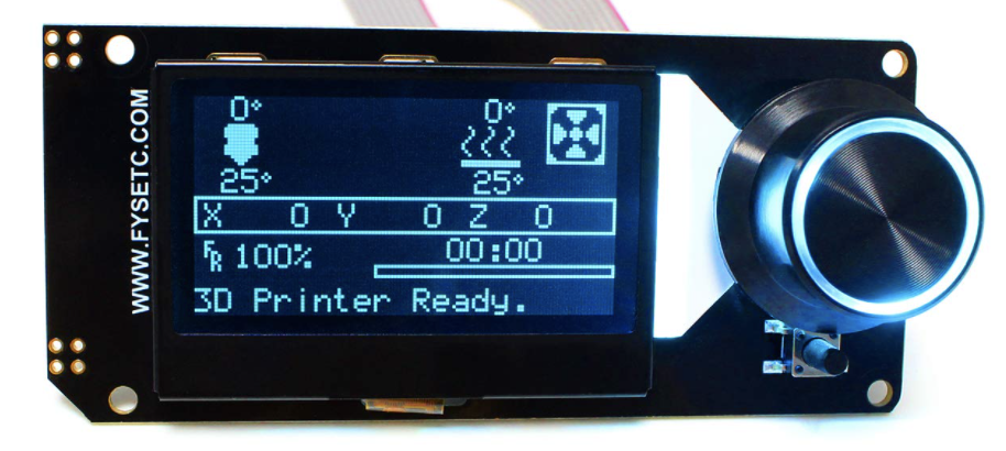
This screen is an excellent option to use together with our FYSETC S6 electronics, since it has a very compact format, is easily integrable and has a great aesthetic. In addition to the inclusion of SD (perfect for updating the firmware) and controllable LEDs from Marlin that always give a lot of play.
So we will leave the configuration here, so that you have no problem adding a display FYSETC MINI 12864 V2.1 (Neopixel) to your 3D printer if you wish.
File “Configuration.h” (FYSETC MINI 12864)
# Definición de pantalla
#define FYSETC_MINI_12864_2_1 // Type A/B. Neopixel RGB Backlight
...
# Definición Neopixel de pantalla
// Support for Adafruit Neopixel LED driver
#define NEOPIXEL_LED
#if ENABLED(NEOPIXEL_LED)
#define NEOPIXEL_TYPE NEO_GRBW // NEO_GRBW / NEO_GRB - four/three channel driver type (defined in Adafruit_NeoPixel.h)
//#define NEOPIXEL_PIN 4 // LED driving pin
//#define NEOPIXEL_PIXELS 30 // Number of LEDs in the strip
//#define NEOPIXEL_IS_SEQUENTIAL // Sequential display for temperature change - LED by LED. Disable to change all LEDs at once.
//#define NEOPIXEL_BRIGHTNESS 127 // Initial brightness (0-255)
#define NEOPIXEL_STARTUP_TEST // Cycle through colors at startup
// Use a single Neopixel LED for static (background) lighting
// #define NEOPIXEL_BKGD_LED_INDEX 0 // Index of the LED to use - Do not
...
// Use a single Neopixel LED for static (background) lighting
#define NEOPIXEL_BKGD_LED_INDEX 0 // Index of the LED to use - Do not change this setting
#define NEOPIXEL_BKGD_COLOR { 0, 255, 0, 0 } // R, G, B, W - We have set green background color as standard
#endif
File “Configuration_adv.h” (FYSETC MINI 12864)
 # Habilitar menus de control LED
 #define LED_CONTROL_MENU
File “Conditionals_post.h” (FYSETC MINI 12864)
These modifications must be made if your screen does not appear letters in a clear / defined way (you can intuit them by viewing them diagonally)
 #elif ENABLED(FYSETC_MINI_12864)
#define _LCD_CONTRAST_MIN 255
#define _LCD_CONTRAST_INIT 255

.../Marlin/src/inc/Conditionals_post.h
Final notes
And well, as Bugs Bunny would say, That’s all folks! From 3DWork we hope that this extensive guide can help you configure your without many headaches.
Or at least serve as an approach to this type of FYSETC electronics that we like so much. Do not forget to initially verify the printer, going over point by point:
- Check limit switches using a terminal (Pronterface, M119 command)
- Check all Homings (XYZ) individually, and if necessary reverse motor rotation
- Check that our thermistors report the temperature correctly
- Check that our bed and hotend heaters work correctly
As always, you can read other interesting articles on our blog:
- BTT SKR 2: How to detect and repair the failure of the first revisions (REV A)
- Elegoo Jupiter 6K: A new flagship arrives on the Crowdfunding platform Kickstarter
- Monoprice Mini Delta v2: The perfect choice to get started in 3D printing
- 3D printed Simpsons TV that plays the episodes randomly
- BigTreeTech SKR 2: Guide and setup of this new electronics
- Complete guide Fysetc Spider: A real “beast” for our 3D printers
- New Marlin Builder v2.0 update (+220 firmwares available v2.0.9.1)
















Déjanos un comentario