Currently, the vast majority of 3D printer manufacturers offer us the filament detection function (or lack of it, to be more precise) as something common.
This means that when our spool of filament runs out, Marlin automatically stops the current job and offers us the ability to insert another spool without losing our current impression.
And although most printers already come with this sensor as standard, it is likely that if you bought yours a few years ago you will not have this interesting functionality. Anyway, this should not worry you, installing a sensor is reduced to modifying a few lines of Marlin code and adding a mechanical (or optical) limit switch.
In today’s article we will address this issue, and you will see that adding it to your printer is not at all complicated. And remember, you can find us daily on our Telegram channel or on our social networks (Facebook , Twitter, Instagram), where you can join our community of 3D printing fanatics.
Brief introduction
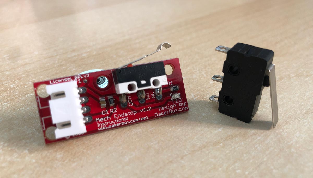
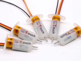
A filament sensor is a simple limit switch (endstop) whose function is simply to detect the possible absence of filament during our impressions. These are usually optical or mechanical.
I use a fairly common and inexpensive mechanical one in my printer. Actually it is not important, both will work without any problem, so the choice of it is in your hands.
There are also cut sensors that various manufacturers sell encapsulated and ready to plug. It is certainly the most comfortable, but sometimes the prices are excessively high.
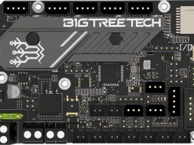
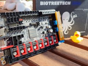
Finally, note that I am using SKR v1.4 Turbo electronics, together with a TFT35 V3.0 Hybrid display. While the Marlin modifications will be for this board, I will add the variations for the other SKR electronics currently available on the market.
In any case, the Runout Sensor functionality (filament detection) is common to Marlin, so regardless of the electronics or display you use, the changes to be made here, except the pins where we will connect the limit switch, are common.
Required components
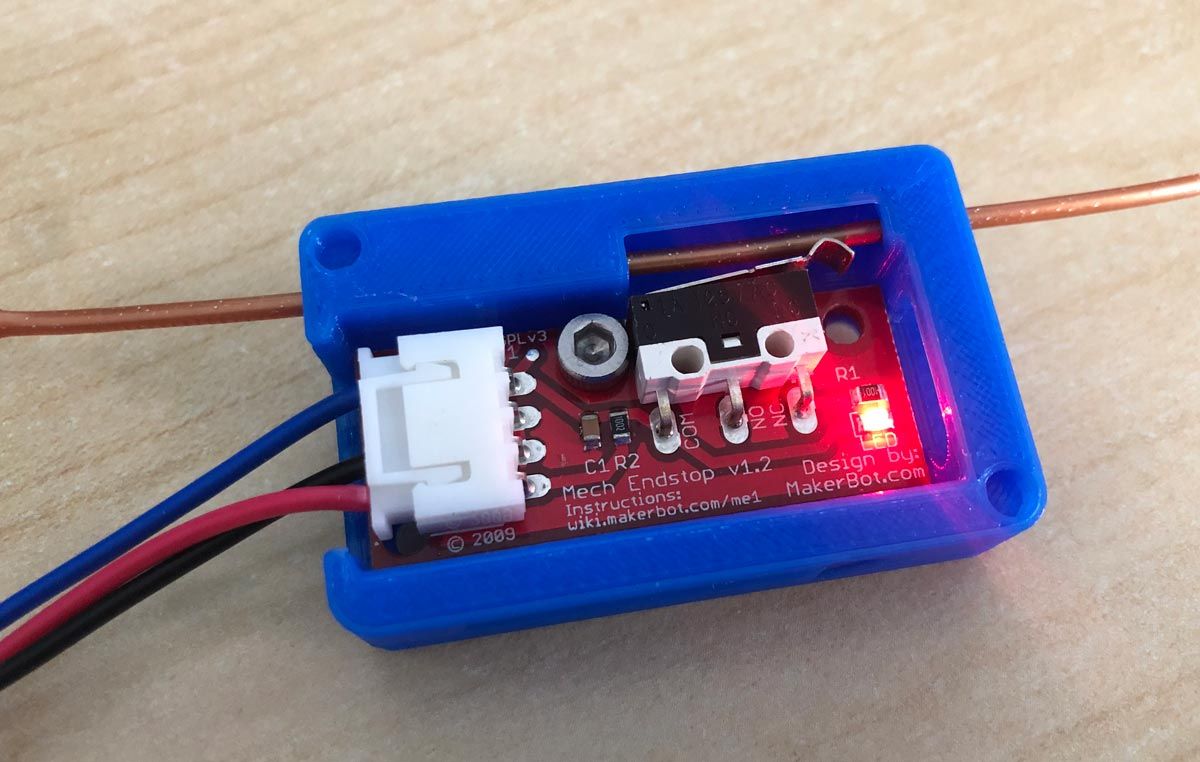
It doesn’t make much sense to buy a sensor for 15 euros when you can simply make one with a limit switch that costs just 1-2 euros.
However I leave you here some links where you can buy the one I use in my printer, as well as some commercials that exist in the market ready to connect.
As you may know beforehand, these links are affiliate links, which means that 3DWork will receive a small commission from the sale, and you will be supporting my website.
| Mechanical endstop | |||
| Optical endstop | |||
| Bigtreetech Sensor (kit) | |||
| Filament sensor (kit) |
Endstop connection to electronics
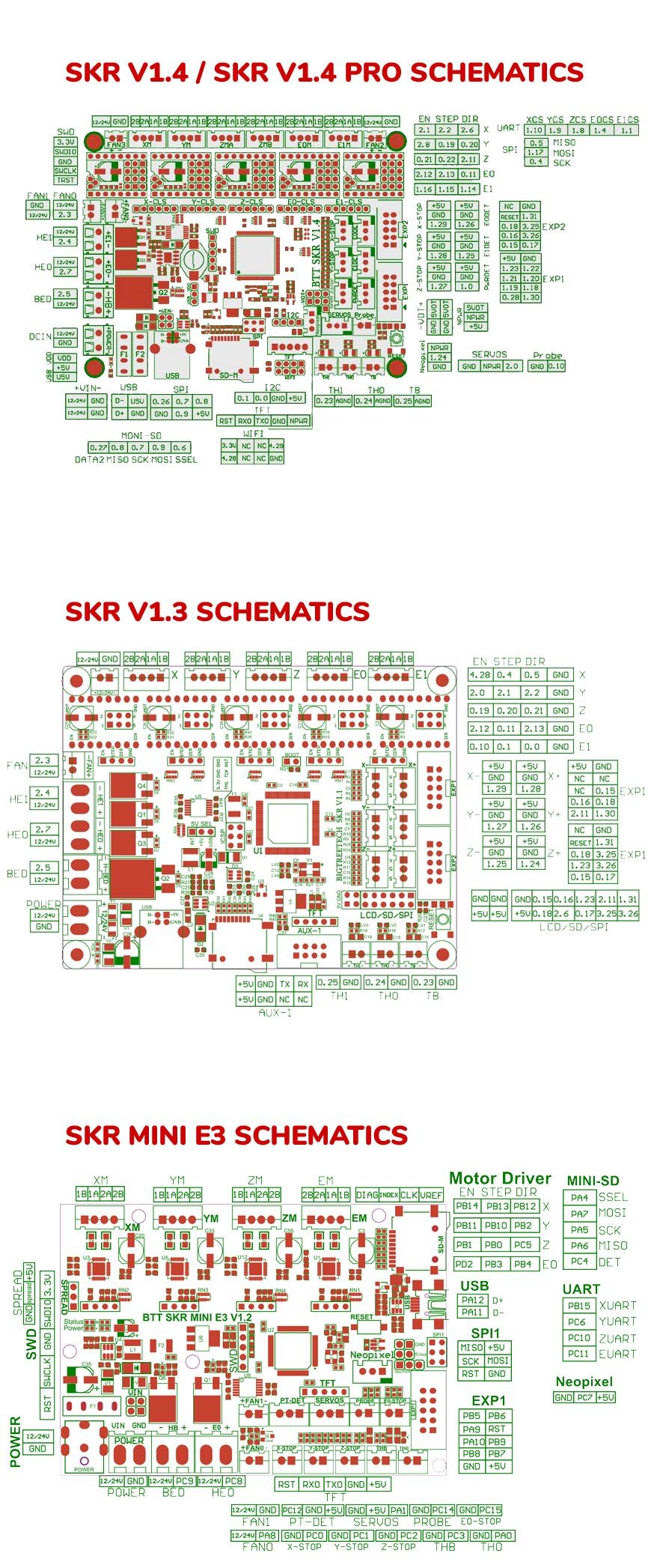
The connection of the sensor to our board will depend on what type of electronics we have. Below I leave you the default pins that we must use, as well as an image with the diagrams that will help you locate the connectors and the different pinouts on the board.
However, for reference, the pin configuration is in your electronics file, in the \Marlin\src\pins folder. Then, you must go to the folder that corresponds to the microprocessor of your board and select the file.
It goes without saying that if you wish, you can change the assignment pins and use another free connector for this function. This way if you have a damaged entry you can move to another with great ease, since Marlin is quite “friendly” in this regard.
It is very important to check the pinout before connecting the sensor to your electronics, otherwise if you make a mistake you could damage it. In my case, my limit switch already came with a 3-wire cable correctly configured and with the possibility of inserting it only in the correct position.
But there are simply 2-wire limit switches, which you must connect to the pins corresponding to C or COM (signal) and GND (ground) in your electronics. Ideally, connect C to the signal pin and NC to ground as it is less prone to possible “noise”. In this way, if the cable were damaged for any reason, it would give the same signal as if you had pressed the limit switch, protecting that the limits of the printer are not exceeded in any case (or in breakage).
Also, some limit switches require removing the PULLUP from the Marlin configuration to operate correctly. If this is your case, you must edit this line and delete the comments:
#define FIL_RUNOUT_PULLUP // Use internal pullup for filament runout pins.
Location of files and schemas
| Electronic board | Files | Pinouts |
| SKR v1.4 Turbo | lpc1768\pins_BTT_SKR_V1_4.h | FIL_RUNOUT_PIN P1_26 (E0DET) FIL_RUNOUT_PIN2 P1_25 (E1DET) |
| SKR v1.4 | lpc1768\pins_BTT_SKR_V1_4.h | FIL_RUNOUT_PIN P1_26 (E0DET) FIL_RUNOUT_PIN2 P1_25 (E1DET) |
| SKR v1.3 | lpc1768\pins_BTT_SKR_V1_3.h | FIL_RUNOUT_PIN P1_28 |
| SKR Mini E3 v1.0 | stm32f1\pins_BTT_SKR_MINI_E3_V1_0.h | FIL_RUNOUT_PIN PC15 (E0-STOP) |
| SKR Mini E3 v1.2 | stm32f1\pins_BTT_SKR_MINI_E3_V1_2.h | FIL_RUNOUT_PIN PC15 (E0-STOP) |
| SKR Mini E3 v2.0 | stm32f1\pins_BTT_SKR_MINI_E3_V2_0.h | FIL_RUNOUT_PIN PC15 (E0-STOP) |
The location of the connectors on the different electronic boards can be found in the following official SKR diagrams. You can click on the image to enlarge it.
Setting up Marlin for our endstop
The configuration could not be simpler, it is simply to modify a few lines of code and we will have the menu available on our display and the autodetection active at all times.
I know modifying Marlin may seem complicated, but nothing could be further from the truth. In the event that you have never modified the firmware, I would recommend that you take a look at a very interesting article that I wrote some time ago.
In it you will find all the necessary information to be able to modify it at will, compile it and upload it to your electronics. You can visit it at the link Complete guide: Configure Marlin 2.0.x from scratch and not die trying
And as a complementary article, in order to use Visual Studio Code and compile 32-bit firmwares, this other must-read article Configure and update your 3D printer using Visual Studio Code and Platform.io
Configuration.h fil
The first thing we are going to do is activate the main function of filament detection. We will edit the Configuration.h file and look for the FILAMENT_RUNOUT_SENSOR function.
By default in Marlin it is deactivated, so we will activate it by eliminating the two characters in front of it “//”. It should look something like this:
#define FILAMENT_RUNOUT_SENSOR
#if ENABLED(FILAMENT_RUNOUT_SENSOR)
#define FIL_RUNOUT_ENABLED_DEFAULT true // Enable the sensor on startup. Override with M412 followed by M500.
#define NUM_RUNOUT_SENSORS 1 // Number of sensors, up to one per extruder. Define a FIL_RUNOUT#_PIN for each.
#define FIL_RUNOUT_STATE HIGH // Pin state indicating that filament is NOT present.
#define FIL_RUNOUT_PULLUP // Use internal pullup for filament runout pins.
//#define FIL_RUNOUT_PULLDOWN // Use internal pulldown for filament runout pins.
Activating this option, we will have the menu available. Now we must check that indeed the sensor is acting as it should. To do this we will execute the gcode M119 command, which will indicate the status of the sensor at all times.
In my case and as I have a hybrid TFT35 BTT display, I can execute gcode commands directly from the screen, something really practical and that saves you time for these tasks.
When executing it and having the sensor correctly configured, the following information appears on the screen:
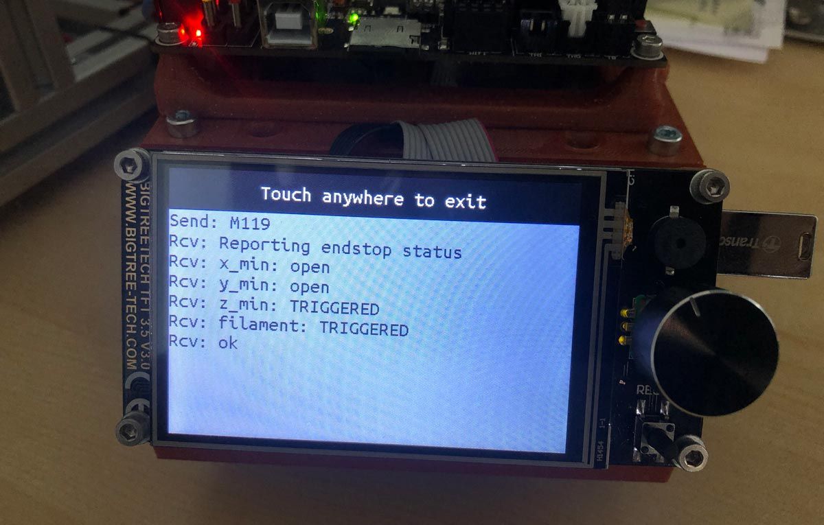
As you can see in the image above, there are two states for the limit switches. OPEN (not pressed) and TRIGGERED (pressed). When the filament is inserted, the sensor must be in the TRIGGERED state since it obviously squeezes the lever.
If not, and it will indicate the OPEN status, you will have to change its logic. To reverse the logic, we will edit a line in the Marlin code, which depending on the Marlin version will be different, so I put the two variants:
Marlin v2.0.6.x or higher
In these firmware versions you must change the state by modifying the word that follows the FIL_RUNOUT_STATE constant, which will be HIGH or LOW. By default Marlin is configured as LOW, so if you need to invert the logic, change it to HIGH.
#define FIL_RUNOUT_STATE HIGH
Marlin lower than v2.0.6.x
In lower versions it is similar, it looks for the constant FIL_RUNOUT_INVERTING and changes the value FALSE to the value TRUE, as simple as that.
#define FIL_RUNOUT_INVERTING false
And finally, in the Configuration.h file, we will activate the NOZZLE_PARK_FEATURE option. We proceed to uncomment the constant so that it looks like this:
#define NOZZLE_PARK_FEATURE false
Configuration_adv.h file
Now it’s the turn of the Configuration_adv.h file, which also requires a very simple last change.
This will activate the advanced printing pause, which includes different functions such as filament loading speed, extraction, purging and many other things.
For this purpose we are going to uncomment the following line:
#define ADVANCED_PAUSE_FEATURE
Final notes
As you have seen, the process of configuring a filament sensor does not present any difficulties. And if you have followed the instructions you should already have the filament sensor active and functional.
It should be noted that although I have a hybrid TFT screen, the detection sensor only works in Marlin mode , since it is not yet fully supported in Touch Screen mode.
Although it does detect the filament cut and tells us to press OK to continue again, when you try it does not respond and remains completely hung. We will wait to see if BigTreeTech can solve this problem in future reviews of the display (or some alternative configuration appears that I am currently unaware of).
Without further ado I say goodbye as always. I hope you find this short useful article useful and I hope to see you soon on our Telegram channel.
I hope this brief introduction to runout filament sensors may have been helpful. Feel free to read other interesting articles from 3DWork.io here:
- Hygroscopy: Moisture issues in 3D Printing Filaments
- Post-processing of 3D parts: Much more resistant and airtight with heat and salt
- Marlin Builder: Update with support for version v2.0.6.1 and factory preconfigured firmwares
- Monoprice Cadet: Safe 3D printing for kids and beginners
- New review of electronic BTT SKR MINI E3 V2.0 for your Ender 3 printer
- Closed-Loop Motors: Makerbase MKS Servo42b (Brief analysis)
- Complete guide SKR v1.4 / v1.4 Turbo with TMC2209 Sensorless drivers and Display TFT35 V3.0











muito bom simples e direto
Thanks for your words 🙂
Regards!
The SKR 1.3 diagram you have in the article is a diagram of a 1.1 not a 1.3. Thanks for the good post.