For some time now the SKR series from BigTreeTech have become a benchmark in the sector when we talk about electronic boards for 3D printing. The latest models SKR v1.4 and SKR v1.4 Turbo they have become extremely popular and it is not surprising to see them as standard in new releases of 3D printers that hit the market.
However, BigTreeTech has other electronic models for 3D printing, with much superior characteristics but not as well known. Two clear examples are the SKR Pro V1.2 and the most recent SKR GTR V1.0 with its expansion board M5 V1 .0, a true delight for the most demanding.
These electronics, especially in the SKR GTR V1.0 + M5 V1.0, are designed specifically for high-performance applications, offering us the possibility of using a multitude of motors with their corresponding sensors and additional electronics.
And as I always do before continuing, I would like to remind you that we have a large community in our Telegram channel, where we share our doubts and experiences. Have no qualms about joining if you wish.
Brief introduction
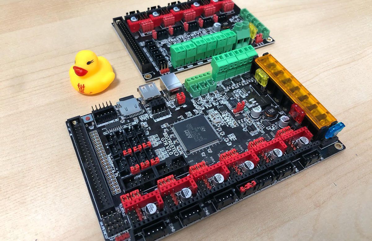
Acquiring an electronics of these characteristics is not something that we should worry too much about if we are going to design or assemble a simple printer (without multiple extrusion). But if your goal is to drastically increase the number of motors or extruders, you should definitely resort to it.
In today’s article I would like to show you the main characteristics of the SKR GTR V1.0 electronics together with the M5 V1.0 expansion module and how to configure them correctly in Marlin with some TMC22xx drivers on the market.
Then you can activate or not the Sensorless feature, an option that I like a lot and that will avoid having to use limit switches on the X and Y axes of our printer.
And regarding the TMC drivers of Trinamic, I recommend you to read a very interesting article that I wrote some time ago about them and about their patents in the following link TMC Drivers: Discover the best drivers for 3D printing and their available technologies.
SKR GTR V1.0 Electronic board
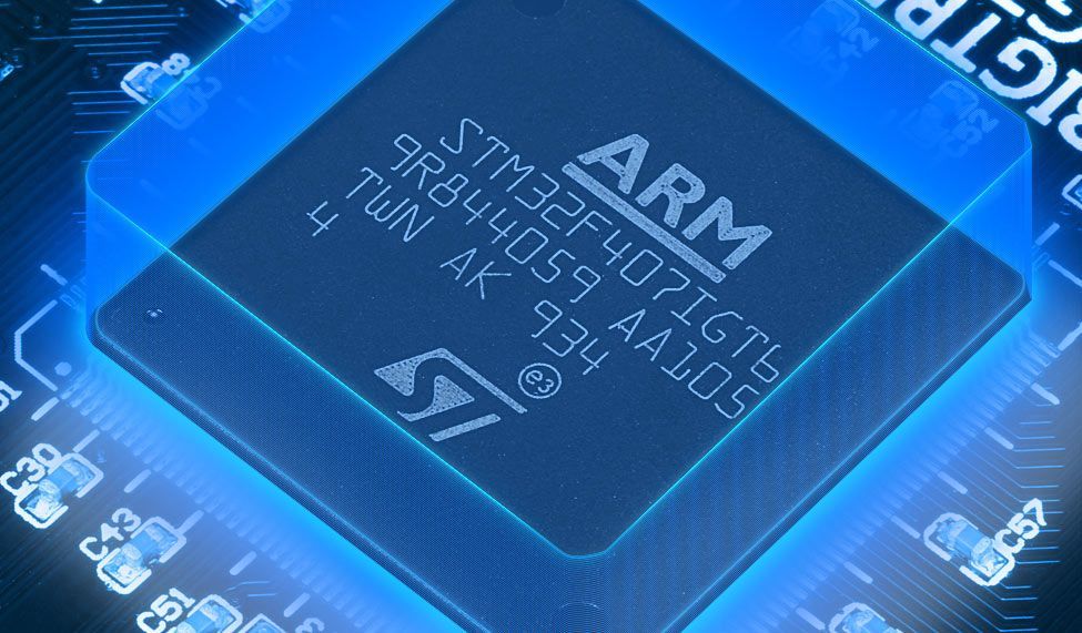
When BigTreeTech prepared the design of this electronic board, it certainly had in mind to offer to the market a high performance application oriented board, this is undeniable. There were two possible ways in this regard, developing clones of the Duet2 together with its own expansion module as other manufacturers did in the past, or designing a new own product (a more than correct decision in my opinion).
The microprocessor of this authentic beast is a Cortex M4 STM32F407IGT6 with 32 bits and offers us clock speeds of up to 168 MHz. And this clock speed is something very unusual in 3D printing devices.
How could it be otherwise, it uses the latest versions of Marlin 2.0.6.x and higher, so that users can customize it without any problem and adapt it to any of their needs.
As indicated in the official manual, you must download a version of Marlin specifically prepared by BigTreeTech for compilation. But as of version 2.0.7.2 you can compile any supported Marlin firmware without any restrictions. We will explain how to do it later.
The electronic board has a design completely thought in the heat dissipation of the same (including high performance Mosfet). A common problem that we often deal with in 3D printing and it supports all types of BTT Touchscreen, LCD2004 and LCD12864 displays.
It also supports 6 motors and 3 fans, being able to expand with 5 motors and 5 more fans, as long as we connect its M5 V1.0 expansion module.
A couple of novelties, compared to other more well-known electronics of the SKR series, is that it includes support for Raspberry Pi as well as possibility of using K-type thermocouples, which they can operate at much higher temperatures than usual thermistors.
Unlimited Multi-extrusion
As you can already imagine, one of the applications that makes the most sense to this electronics is multi-extrusion. And when I say multi-extrusion I do not mean 2 filament extruders but 4, 6 and even 8 that we can support with the SKR GTR V1.0 and its expansion module M5 V1.0.
Obviously you can mount multi-extrusion on any 3D printer, since the only limit here is the electronics of the machine, but the prices so far with the electronics available were exorbitant.
This is an example of a commercial printer from the E3D manufacturer where it shows 4 extruders and their management, thanks to the ToolChanger system that uses servos to make the changes.
Certainly very few electronics support these features, in fact the E3D Motion System uses an electronic board Duet + Expansion Module for this. With the new SKR GTR V1.0 you could even fit 11 engines, something that not even the Duet supports at the moment, and for less than half the price of it.
This makes clear the potential of this new series of electronics that BigTreeTech is launching on the market and raises the bar for the rest of the manufacturers, something that we love as it forces the competition to improve their products.
Where to buy the SKR GTR V1.0
Here you can find links to some marketplaces where to find this electronic board. It is my duty as always to inform you that they are affiliate links.
If you use them, the price of the product will be the same as if you log in regularly, but 3DWork will have a small commission that will help maintain the website.
| SKR GTR V1.0 | |||
| SKR GTR V1.0 + M5 V1.0 |
You can also use our specific search engine for 3D printing products called Markets.sx. This way you will literally crawl different online marketplaces in a single click (Amazon, Gearbest, Aliexpress, etc.) and show you the results in a single search.
Comparing SKR V1.4 Turbo and SKR GTR V1.0
In order to see the main differences at a glance, I leave you a brief comparative table with both plates and some of their corresponding technical specifications.
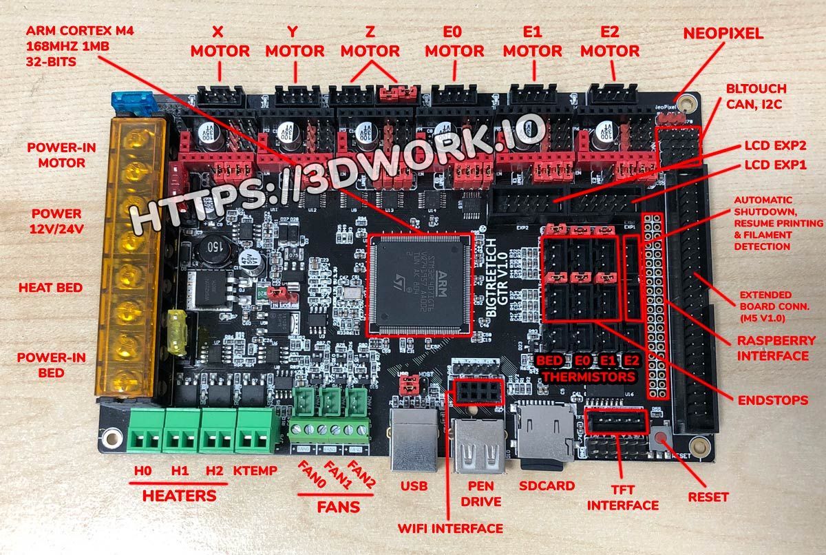
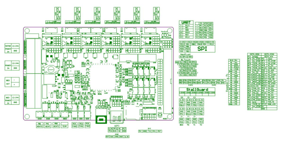
If you want to go into details, later in the article you have the complete diagrams and connection of the SKR GTR V1.0 and its expansion board, the SKR M5 V1.0.
| SKR V1.4 TURBO | SKR GTR V1.0 + M5 V1.0 | |
| CPU Frequency | LPC1769 Cortex M3 (120 MHz) | STM32F4 Cortex M4 (168 MHz) |
| Motor driver interfaces | 5 | 11 |
| Fan interfaces | 4 | 8 |
| Temp. sensors | 3 Thermistors | 9 Thermistors + 2 K-Temp |
| Endstops | 3 Endstops | 11 Endstops |
| Neopixel connectors | 1 | 2 |
| Raspberry Pi support | no | yes |
Feeding our SKR GTR V1.0
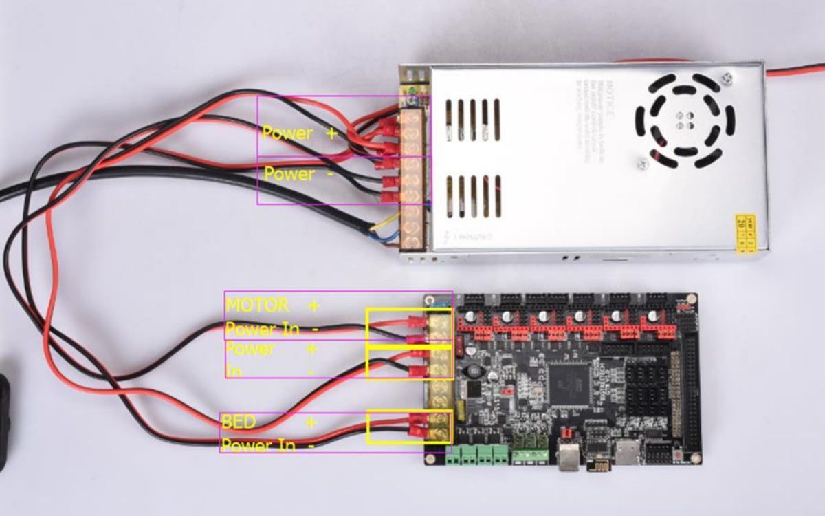
An important detail to have in mind is that you will need to power the SKR GTR V1.0 electronics with 3 cables from your main source. As you can see, the power lines to the board, the motors and the heated bed are completely separated.
In the image above I show you the proper way to wire the SKR GTR V1.0. It may seem somewhat cumbersome, but when you buy the electronics, it brings 3 power cables prepared for this purpose, so you should not have any complications.
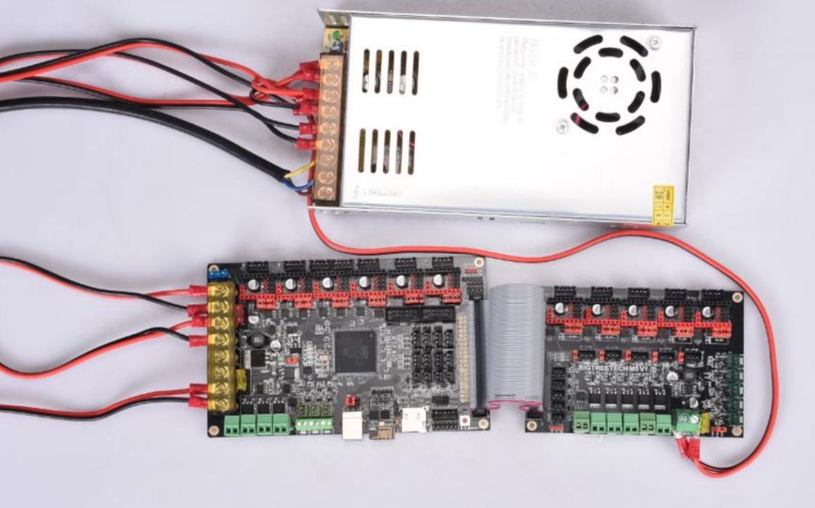 If in addition to the SKR GTR V1.0 you are going to connect your SKR M5 V1.0 expansion board, you must add an extra power line, which in this case would be the fourth, and which would also be connected to the same source.
Here is another image with an M5 connected to its corresponding GTR and to the power supply (click to enlarge the image).
And finally check the polarity of the cables when making the connections . It is something that I always like to remember, since otherwise you could damage the electronics (or electronics) if you make a mistake in the connections from your source.
Electronic diagrams and connections
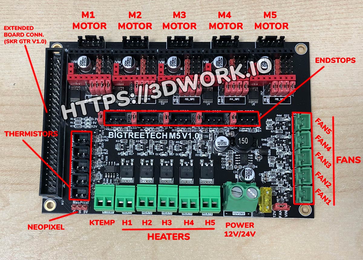
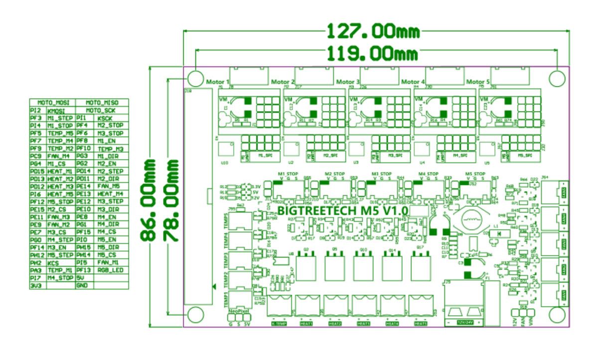
Here you have the schematics of the SKR GTR and SKR M5 (expansion module) as well as the different connectors in each of the two. If you wish, you can enlarge the images by clicking on them:
SKR GTR V1.0
SKR M5 V1.0 (Expansion module)
Downloading Marlin firmware (Github)
SKR GTR V1.0 electronics use their own Marlin firmware, which you must download from the BigTreeTech support area (Official Github) as we have commented a few lines above. However, this firmware is in version v2.0.6.2, which although very recent, is no longer the latest version of Marlin (as of this writing, the latest version is v2.0.7.2).
So directly I recommend that you download the firmwares from the official Marlin website, and of course the latest version available. Before, Marlin did not have official support for this new electronics, but since version v2.0.7.2 it is fully supported.
You can find the links to download the latest firmware on the following web page (marlinfw.org). Once in your possession, unzip it on your desktop and you can start modifying it to your liking.
Before continuing with two brief sections, the first is that I used a BigTreeTech TFT35 V3.0 display for this guide, which can operate in two modes (marlin and touchscreen). Simply if you do not have this display, you will have to modify a line of code about it and voila, it has no major difficulty.
The second section is that to edit and compile our firmware you must use a text editor called Visual Studio Code, along with its Platformio extension.
If you do not have any experience with it, I recommend that you read a very interesting article that I wrote some time ago. In this way you will learn to edit, compile and upload your Marlin firmware for 8-bit and 32-bit boards (which is our case).
You can consult the article in the following link: Configure and update your 3D printer using Visual Studio Code and Platform.io and, of course, download the software for free.
Configuring Marlin for the SKR GTR V1.0
In this configuration guide for your SKR GTR V1.0 electronics I will ignore everything related to the mechanics of your 3D printer and will only mention the parameters to configure for the SKR GTR V1.0, the TFT35 V3.0 display, and the TMC22xx drivers (in UART + Sensorless smart mode).
This does not mean that you are left without information about it, in fact a while ago I wrote another article on how to configure Marlin on any Cartesian 3D printer. Ideally, you should access it beforehand to configure your printer before continuing this article.
You can access the article at the following link: Guía completa: Configurar Marlin 2.0.x desde cero y no morir en el intento.
«Platformio.ini» file
The first file that we are going to modify is the «Platformio.ini» to tell our compiler what type of microprocessor or electronics we have. If we do not indicate Visual Studio Code it would have problems when compiling our firmware.
This file is inside the Marlin firmware, exactly in the root directory, so you should find it very easily. We will edit Platformio.ini and in the field «default_envs» we will put our electronic board.
In our case, the value to put would be «BIGTREE_GTR_V1_0» and it would look like this:
[platformio]
src_dir      = Marlin
boards_dir   = buildroot/share/PlatformIO/boards
default_envs = BIGTREE_GTR_V1_0
include_dir  = Marlin
“Configuration.h” file
Now it is time to modify the file “Configuration.h” that takes care of the general configurations of our printer. We are going to indicate the type of electronics, ports, speed and some more parameters.
We will start with the parameters to configure the communication ports (primary and secondary) and the communication speed. In this last parameter I usually put 250,000bds but if you experience any problems, slow down and use 115,200bds.
/**
* Select the serial port on the board to use for communication with the host.
* This allows the connection of wireless adapters (for instance) to non-default port pins.
* Serial port -1 is the USB emulated serial port, if available.
* Note: The first serial port (-1 or 0) will always be used by the Arduino bootloader.
*
* :[-1, 0, 1, 2, 3, 4, 5, 6, 7]
*/
#define SERIAL_PORT -1

/**
* Select a secondary serial port on the board to use for communication with the host.
* :[-1, 0, 1, 2, 3, 4, 5, 6, 7]
*/
#define SERIAL_PORT_2 3
/**
* This setting determines the communication speed of the printer.
*
* 250000 works in most cases, but you might try a lower speed if
* you commonly experience drop-outs during host printing.
* You may try up to 1000000 to speed up SD file transfer.
*
* :[2400, 9600, 19200, 38400, 57600, 115200, 250000, 500000, 1000000]
*/
#define BAUDRATE 250000
Now you must tell Marlin exactly what type of electronic board we are assembling. In this table you can see different SKR electronics models and on their right the parameter that you must enter.
| Electronic board type | Parameter |
| SKR v1.1 | BOARD_BTT_SKR_V1_1 |
| SKR v1.3 | BOARD_BTT_SKR_V1_3 |
| SKR v1.4 | BOARD_BTT_SKR_V1_4 |
| SKR v1.4 Turbo | BOARD_BTT_SKR_V1_4_TURBO |
| SKR Pro v1.1 | BOARD_BTT_SKR_PRO_V1_1 |
| SKR Pro v1.2 | BOARD_BTT_SKR_PRO_V1_2 |
| SKR Mini E3 V1.2 | BOARD_BTT_SKR_MINI_E3_V1_2 |
| SKR Mini E3 V2.0 | BOARD_BTT_SKR_MINI_E3_V2_0 |
| SKR GTR v1.0 | BOARD_BTT_GTR_V1_0 |
In our case, mounting a SKR GTR V1.0 electronics, it would be as follows:
// Choose the name from boards.h that matches your setup
#ifndef MOTHERBOARD
#define MOTHERBOARD BOARD_BTT_GTR_V1_0
#endif
Then we are going to configure the type of driver that we have and the motors in which they are mounted. We will look for the following lines and add them. You have a multitude of different drivers, so if yours was not TMC2209 change it to the one you are going to install.
/**
* Stepper Drivers
*
* These settings allow Marlin to tune stepper driver timing and enable advanced options for
* stepper drivers that support them. You may also override timing options in Configuration_adv.h.
*
* A4988 is assumed for unspecified drivers.
*
* Options: A4988, A5984, DRV8825, LV8729, L6470, L6474, POWERSTEP01,
*          TB6560, TB6600, TMC2100,
*          TMC2130, TMC2130_STANDALONE, TMC2160, TMC2160_STANDALONE,
*          TMC2208, TMC2208_STANDALONE, TMC2209, TMC2209_STANDALONE,
*          TMC26X,  TMC26X_STANDALONE,  TMC2660, TMC2660_STANDALONE,
*          TMC5130, TMC5130_STANDALONE, TMC5160, TMC5160_STANDALONE
* :['A4988', 'A5984', 'DRV8825', 'LV8729', 'L6470', 'L6474', 'POWERSTEP01', 'TB6560', 'TB6600', 'TMC2100', 'TMC2130', 'TMC2130_STANDALONE', 'TMC2160', 'TMC2160_STANDALONE', 'TMC2208', 'TMC2208_STANDALONE', 'TMC2209', 'TMC2209_STANDALONE', 'TMC26X', 'TMC26X_STANDALONE', 'TMC2660', 'TMC2660_STANDALONE', 'TMC5130', 'TMC5130_STANDALONE', 'TMC5160', 'TMC5160_STANDALONE']
*/
#define X_DRIVER_TYPE  TMC2209
#define Y_DRIVER_TYPE  TMC2209
#define Z_DRIVER_TYPE  TMC2209
//#define X2_DRIVER_TYPE A4988
//#define Y2_DRIVER_TYPE A4988
//#define Z2_DRIVER_TYPE A4988
//#define Z3_DRIVER_TYPE A4988
//#define Z4_DRIVER_TYPE A4988
#define E0_DRIVER_TYPE TMC2209
//#define E1_DRIVER_TYPE A4988
//#define E2_DRIVER_TYPE A4988
//#define E3_DRIVER_TYPE A4988
//#define E4_DRIVER_TYPE A4988
//#define E5_DRIVER_TYPE A4988
//#define E6_DRIVER_TYPE A4988
//#define E7_DRIVER_TYPE A4988
And to finish with the edition of the “Configuration.h” file, we will edit two other very important parameters that we cannot forget. The first one will help us to activate the Marlin emulation on our display.
And the second parameter will allow us to support eeprom storage in our printer, it is also essential to activate it.
//
// RepRapDiscount FULL GRAPHIC Smart Controller
// http://reprap.org/wiki/RepRapDiscount_Full_Graphic_Smart_Controller
//
#define REPRAP_DISCOUNT_FULL_GRAPHIC_SMART_CONTROLLER
/**
* EEPROM
*
* Persistent storage to preserve configurable settings across reboots.
*
*   M500 - Store settings to EEPROM.
*   M501 - Read settings from EEPROM. (i.e., Throw away unsaved changes)
*   M502 - Revert settings to "factory" defaults. (Follow with M500 to init the EEPROM.)
*/
#define EEPROM_SETTINGS     // Persistent storage with M500 and M501
“Configuration_adv.h” file
Once we have finished configuring the first file, we will go to “Configuration_adv.h“, which is responsible for managing more advanced options of our 3D printer, as well as other experimental or under development.
The first parameter that you must modify is the interpolation of steps, in this way we will let our driver manage them automatically.
#define INTERPOLATE true // Interpolate X/Y/Z_MICROSTEPS to 256
The next thing to do is indicate the voltage we want to supply to our drivers and the microsteps at which they must operate. As I only have 4 axes (X, Y, Z and E0), these will be the lines to configure and the standard values that we will put initially.
#if AXIS_IS_TMC(X)
#define X_CURRENT       850        // (mA) RMS current. Multiply by 1.414 for peak current.
#define X_CURRENT_HOME  X_CURRENT  // (mA) RMS current for sensorless homing
#define X_MICROSTEPS     16    // 0..256
#define X_RSENSE          0.11
#define X_CHAIN_POS      -1    // <=0 : Not chained. 1 : MCU MOSI connected. 2 : Next in chain, ...
#endif

#if AXIS_IS_TMC(Y)
#define Y_CURRENT       850
#define Y_CURRENT_HOME  Y_CURRENT
#define Y_MICROSTEPS     16
#define Y_RSENSE          0.11
#define Y_CHAIN_POS      -1
#endif

#if AXIS_IS_TMC(Z)
#define Z_CURRENT       850
#define Z_CURRENT_HOME  Z_CURRENT
#define Z_MICROSTEPS     16
#define Z_RSENSE          0.11
#define Z_CHAIN_POS      -1
#endif

#if AXIS_IS_TMC(E0)
#define E0_CURRENT      600
#define E0_MICROSTEPS    16
#define E0_RSENSE         0.11
#define E0_CHAIN_POS     -1
#endif
We will indicate to Marlin the voltage that our power supply supplies, which are usually 12V or 24V usually, in this way:
/**
* Optimize spreadCycle chopper parameters by using predefined parameter sets
* or with the help of an example included in the library.
* Provided parameter sets are
* CHOPPER_DEFAULT_12V
* CHOPPER_DEFAULT_19V
* CHOPPER_DEFAULT_24V
* CHOPPER_DEFAULT_36V
* CHOPPER_PRUSAMK3_24V // Imported parameters from the official Prusa firmware for MK3 (24V)
* CHOPPER_MARLIN_119   // Old defaults from Marlin v1.1.9
*
* Define you own with
* { <off_time[1..15]>, <hysteresis_end[-3..12]>, hysteresis_start[1..8] }
*/
#define CHOPPER_TIMING CHOPPER_DEFAULT_24V
We will activate the temperature protections that Marlin offers for our Trinamic drivers with the MONITOR_DRIVER_STATUS parameter:
/**
* Monitor Trinamic drivers for error conditions,
* like overtemperature and short to ground.
* In the case of overtemperature Marlin can decrease the driver current until error condition clears.
* Other detected conditions can be used to stop the current print.
* Relevant g-codes:
* M906 - Set or get motor current in milliamps using axis codes X, Y, Z, E. Report values if no axis codes given.
* M911 - Report stepper driver overtemperature pre-warn condition.
* M912 - Clear stepper driver overtemperature pre-warn condition flag.
* M122 - Report driver parameters (Requires TMC_DEBUG)
*/
#define MONITOR_DRIVER_STATUS
Now, and only in the case that you want to activate Sensorless in your printer, you must activate the SENSORLESS_HOMING parameter by uncommenting it from the Marlin code. Once uncommented you can use the X_STALL_SENSITIVITY and Y_STALL_SENSITIVITY options to configure the sensitivity.
A value close to 0 means that the motor will not stop when faced with an obstacle, and a value close to 255 deactivates the movement of the motor to the minimum obstacle. The recommended value would be to leave it at 100, as I have in the code that I show you below:
#define SENSORLESS_HOMING // StallGuard capable drivers only

#if EITHER(SENSORLESS_HOMING, SENSORLESS_PROBING)
// TMC2209: 0...255. TMC2130: -64...63
#define X_STALL_SENSITIVITY  100
#define X2_STALL_SENSITIVITY X_STALL_SENSITIVITY
#define Y_STALL_SENSITIVITY  100
//#define Z_STALL_SENSITIVITY  8
//#define SPI_ENDSTOPS              // TMC2130 only
//#define IMPROVE_HOMING_RELIABILITY
#endif
And to finalize two more parameters. SQUARE_WAVE_STEPPING to have a more precise signal in our drivers (we recommend activating it) and TMC_DEBUG, to be able to debug and know the status of our drivers in real time, very useful if we have pre-configured smart UART mode.
/**
* Beta feature!
* Create a 50/50 square wave step pulse optimal for stepper drivers.
*/
#define SQUARE_WAVE_STEPPING
/**
* Enable M122 debugging command for TMC stepper drivers.
* M122 S0/1 will enable continuous reporting.
*/
#define TMC_DEBUG
And so far everything is ready as far as the Marlin firmware edition is concerned. As you can see, there have not been excessive changes. Let’s now go on to configure our display.
Upgrading TFT35 V3.0 Display
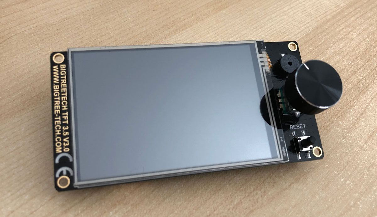
Although I have always been in favor of using the original Marlin menu (with LCD12864 displays), since I tested the TFT35 V3.0 displays I usually mount this electronics on my machines.
Believe me if I tell you that they work really well, they are hybrids (they allow you to switch modes in real time between TouchScreen and Marlin) and the support in TouchScreen mode could not be more complete, since it includes practically all the mod options you can imagine.
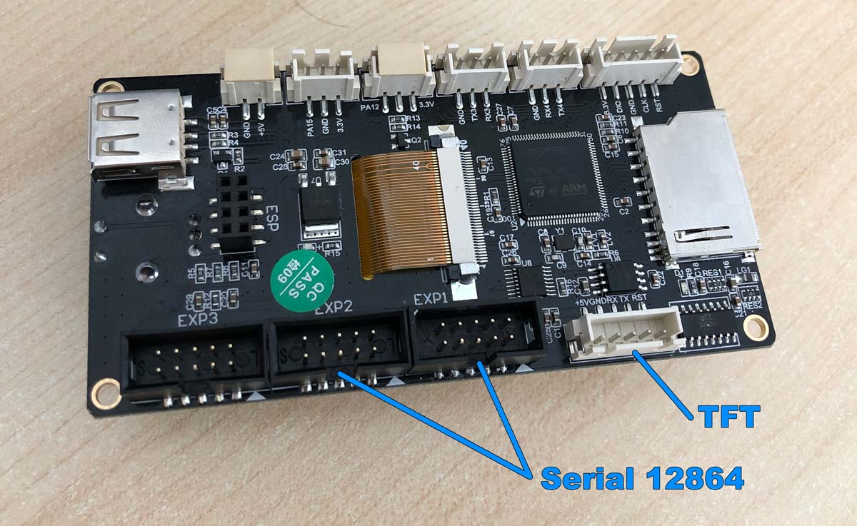 In order to use both modes, you must make 3 connections to the SKR GTR V1.0 electronics.
Two will be the typical 2×5-pin flat cables that are always used with LCD12864 displays, and another will be the specific connector for the TFT, as you can see in this image (click to enlarge).
To switch between the two interface modes (Marlin or TouchScreen) you just have to press the button for 3 seconds and select the desired option, which is easier than ever.
As I mentioned in the previous section where we modified the “Configuration.h” file, uncommenting the REPRAP_DISCOUNT_FULL_GRAPHIC_SMART_CONTROLLER parameter would be enough to configure it and we would have it fully operational.
However, I would recommend updating the display to the latest version available, since I have seen some users with problems using not too recent firmwares on their SKR GTR V1.0 electronics.
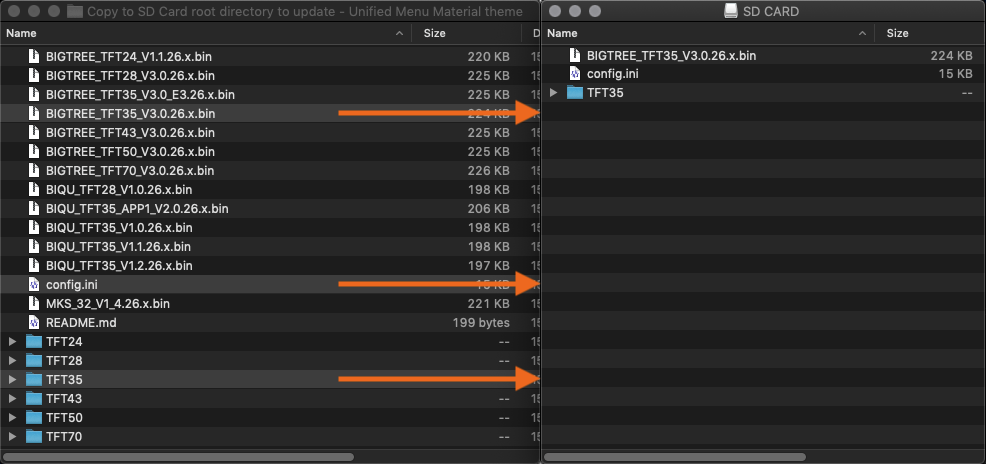 Updating it is a very simple process, you just have to copy to a memory card 2 files (config.ini and BIGTREE_TFT35_V3.0.26.x.bin) and 1 directory (/TFT35), connect this same memory to the screen and turn it on (click on image to enlarge).
The update process will run automatically and in about a minute you will have the update ready. Files can be downloaded directly from this link. I have chosen the interface with design “Unified Menu Material Theme“, since it seems more elegant and simpler to me, although you can always change to “Classic menu” available in this other link.
Finally, indicate that you also have various configuration parameters in your “config.ini” file, which you can modify with your favorite text editor and always before uploading it to the memory card for the update process. Here it is important that the baud rate is the same that we have configured in Marlin (250,000bds), otherwise our display will not detect the 3D printer.
For more information, please do not hesitate to consult the official documentation that you will find in the BigTreeTech Github.
TMC Driver Configuration (UART/SPI)

Here you have the configuration of some SKR GTR V1.0 electronic drivers to operate in intelligent modes (UART/SPI). Depending on the manufacturer and the board revision, it is possible that you may need different configurations to carry out the connection correctly.
In this section I will show you some drivers, which will not be all at the beginning, and as I find more information I will complete the article.
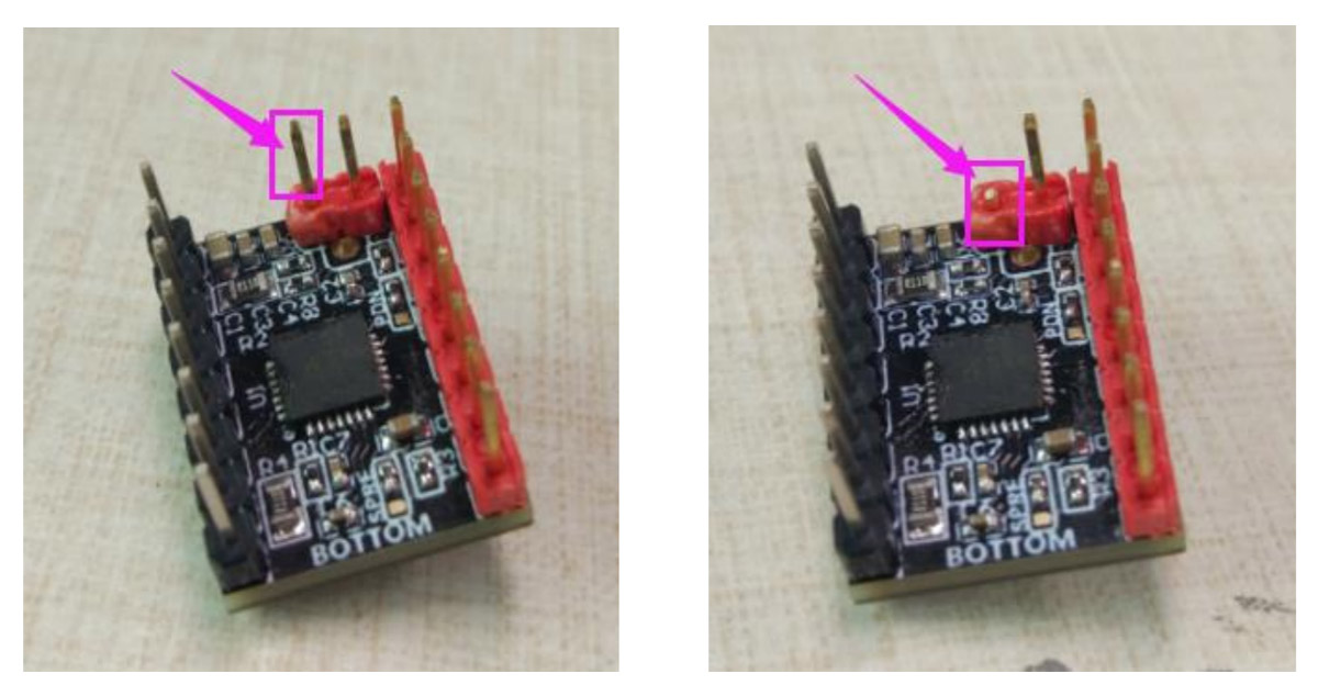
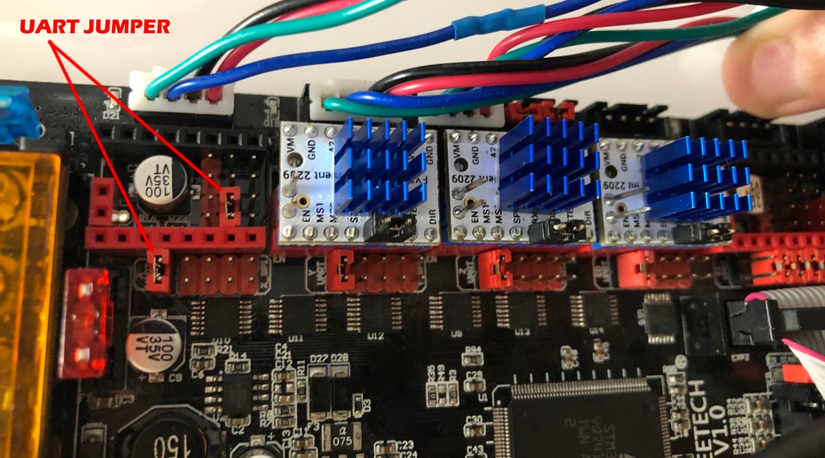
Finally, indicate that according to the manufacturer’s documentation, if you only want the intelligent UART mode and you are going to continue using mechanical limit switches for the X and Y motors, they recommend cutting a pin from the driver as you can see in this image (click to enlarge).
Since cutting seems a bit drastic to me personally, you can choose to carefully fold it to one side. In this way, if in the future you want to change the configuration and use them in Sensorless mode (without mechanical limit switches), you can do it without any problem.
Makerbase TMC2208 V2.0 (UART)
Makerbase TMC2209 V2.0 (UART + Sensorless)
Makerbase TMC2225 V1.0 (UART)
BigTreeTech TMC2208 V3.0 (UART)
BigTreeTech TMC2209 V1.1/V1.2 (UART + Sensorless)
BigTreeTech TMC2225 V1.0 (UART)
BigTreeTech TMC2226 V1.0 (UART + Sensorless)
The Trinamic TMC2225 drivers are an update of the TMC2208 but with a different package (HTSSOP). Otherwise and according to the manufacturer’s specifications they are identical.
However, this new encapsulation of the TMC2225 offers us a greater thermal resistance of the driver, since it greatly improves its cooling compared to its predecessor the TMC2208. And if your electronics do not have cooling, I would choose to choose them, compared to the TMC2208.
They do not have the patented StallGuard technology , which does not give us the possibility of configuring our printer in Sensorless mode (without limit switches). But you can configure them in UART mode to be able to monitor them and access other interesting functions (such as the amperage configuration of our drivers), something that is recommended and practical.
On the TMC2226 as more of the same, another update of the already known TMC2209 with identical specifications, but with new packaging (HTSSOP), little more to add. And as I like to remember, if you want to know more about these fabulous Trinamic drivers be sure to consult this article: TMC Drivers: Discover the best drivers for 3D printing and their available technologies
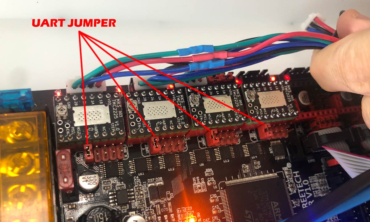
The way to configure these drivers listed above with our GTR SKR V1.0 electronics is identical. As you can see in the image above, you simply have to put a single jumper in the first position, and eliminate the rest of the jumpers that are connected to the board, including those that are located under the same driver.
FYSETC TMC2209 V3.0 (UART + Sensorless)
FYSETC is another important manufacturer of electronics for 3D printing and, of course, its own drivers. Among its catalog it has the FYSTEC TMC2209 V3.0, which you must configure as it appears in the photo above (click on the image to enlarge).
It would simply be to put the same jumper that we use in the other driver models in the UART position, and then under the driver place another jumper in that position that appears in the image. And they would already be configured for UART mode without any problem.
Some final recommendations
It is likely that after compiling the Marlin firmware and uploading it to your electronics an Eeprom error will appear on your screen. If this is the case, don’t worry as it is common after installing a new firmware.
You should run these g-code commands one by one (don’t just insert them all at once) and the problem will be fixed. The commands are M502, M500 and M501 in this same order. I leave you right here the description of what each of them does.
- M502 – Complete reset to factory settings. It does not require the EEPROM_SETTINGS parameter.
- M500 – Saves all current configuration to our EEPROM.
- M501 – Loads the current values from the EEPROM.
In the latest versions of Marlin, and quite rightly, the programmers have added a new option that tells you if the Eeprom is corrupt. If this is the case, Marlin offers you the possibility of resetting it with a simple button click, so it is not something to worry about excessively.
And well, this would be all the basics to get your new electronics going. I didn’t think the article was going to get that long certainly. However, and due to its length, I do not rule out that some misprints may have “slipped” into it. If this is the case, I apologize in advance and let me know so I can correct it on the fly.
Most of the drivers I have tested myself, but they are not nearly all the ones currently available on the market. If you have one that is not reviewed and you want to share with me its UART configuration, I will very gladly add it for the entire 3DWork community.
So nothing more, I say goodbye wishing that this reading could have been of interest to you. Other cool articles from 3DWork.io:
- Adding filament sensor in SKR electronics (MINI E3, v1.3, v1.4 and v1.4 Turbo)
- Hygroscopy: Moisture issues in 3D Printing Filaments
- Post-processing of 3D parts: Much more resistant and airtight with heat and salt
- Marlin Builder: Update with support for version v2.0.6.1 and factory preconfigured firmwares
- Monoprice Cadet: Safe 3D printing for kids and beginners
- New review of electronic BTT SKR MINI E3 V2.0 for your Ender 3 printer
- Closed-Loop Motors: Makerbase MKS Servo42b (Brief analysis)
- Complete guide SKR v1.4 / v1.4 Turbo with TMC2209 Sensorless drivers and Display TFT35 V3.0











Wrong statement: “And when I say multi-extrusion I do not mean 2 filament extruders but 4, 6 and even 8 that we can support with the SKR GTR V1.0 and its expansion module M5 V1.0.”
M5 termistor filters are not working correct. There is jitter on all M5 termal ports so you can´t use non of the M5 motors for driving additional extruders!
Too Endstop layout is now 3.3 Volt – in difference to most older BTT Boards, where it was 5V. So you´re too limited in this.
I´m using this combo now for nearmost a year and it turns out to be a really poor solution.
Hello Charly,
I not tested in real all this amount of extruders, just exposed the possibilities of this electronic board knowing factory specifications. Will be good to know from yourself how many extruders max. you configured properly with this board as it seems you deeply tested it.
Thanks a lot for share all this information and thoughts with us here,
Best regards!
GTR allows X1 Y1 Z1 and E0 E1 E2 with working termistor ports for E1-3
M5 has theoretically 5 additional ports- but termistors don´t work on this board without strong jitter. So you can´t use none of them for driving separate extruders E3-E7.
All you can use M5 additonal ports for is Z2 (automatic G34 2 -axis Z Steppers Auto-Alignment) or Z2-Z4 (automatic G34 4 axis Z Steppers Auto-Alignment) and X2 (or Y)2 to have multi motor power on bed movements in one direction.
Could not find any additional servo port on M5. Only Neo-Pixel Port on M5 can be used for servos – but has same pin no as Neo-Pixel Port on GTR – so no additonal servo port on this. (GTR ist told to have 4 servo-ports until now only could locate 3 functional servo ports)
You can also run Duetwebcontrol and RRF on this board now, with no restrictions. So its become a real duet contender on every axis now.
Thanks a lot for your comment, for sure will be interesting for GTR owners 🙂
Regards!
I bought a GTR v1.0 and I can’t get the endstop to work, when I trigger it or not manually, on the pronterface, the result is always the same, I already inverted the Mechanical endstop, I inverted the engines and nothing makes the cars stop, there will be some configuration that escapes me?
I appreciate the help
thank you
Hi, i am adding a 220v silicone bed to my machine with a ssr module. So the positive and negative cables from the ssr goes to ”Bed Power Out” port to trigger the heat bed right?
Hi, i am adding a 220v silicone bed to my machine with a ssr module. So the positive and negative cables from the ssr goes to ”Bed Power Out” port to trigger the heat bed right?