Recently some users of the Telegram channel were interested in how to configure Marlin 2.0.x and they exposed it in the group. Having seen what I saw I thought, Why not write a complete guide to configure Marlin step by step?
It was something that had been on my mind for a long time, since my printers continued to work with an old version of firmware (specifically v1.1.9). So without further ado I got down to work and started writing.
Brief introduction
This guide is not intended to be a boring and tedious Marlin manual. I will simply show you the essential (or more basic) options to consider to configure Marlin quickly.
I will use as an example a “Custom” printer that I designed some time ago, and step by step you will discover where and how to configure Marlin 2.0.x successfully for your 3D printer.
But I would like to indicate 2 important things before starting. The first is that my mother tongue is Spanish, so I try to write the articles in Spanish and English, but the English version of the article may have some misprints. If so, I apologize in advance.
And the second is that perhaps there is some parameter that due to the mechanics of your printer does not appear in the article. If so, and you have read the guide completely, you will already understand how Marlin works, and I am sure that it will not be difficult to find it in the Firmware.
At the end of the day the goal is for you to learn to cope with Marlin yourself and lose your fear, and not to depend on guides like this.
Here is the index, so if you need it you can access a specific parameter to consult more quickly. Let’s go then with the article without further delay…
Configure Marlin 2.0.x from scratch
I highly recommend that you follow the order of the article when setting it up. The reason is that the parameters will also be found in the same order when you edit the firmware. And in this way you will not run the risk of leaving one on the way.
The most important thing is to lose your fear of Marlin, and if this article helped you it would have more than fulfilled its objective. Knowing Marlin you will understand and enjoy a little more the exciting world of 3D printing and all its possibilities.
And if you have any questions along the way, you can always share them on our Telegram. Surely a partner will be more than willing to give you a cable.
Introduction to Marlin 2.0.x
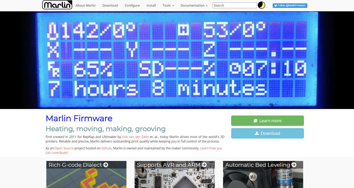
Configure Marlin 2.0.x on your printer can seem like a challenge at first glance and something only seasoned programmers can achieve. But that statement couldn’t be further from the truth, believe me.
With a little patience and a good text editor, we can configure any arduino-based printer with the latest firmware versions without any problem (and without programming knowledge). In fact, Marlin is made up of many, many files, but we will only need to modify one or two at the most to compile a working firmware and then upload it to our printer.
Of course, you can customize Marlin 2 as much as you want, but we already need to modify quite a few files that we will not mention at the moment or that we will do later.
You are probably wondering why you need have to learn to configure Marlin 2.0.x. The answers can be diverse, but the one that convinces me the most is that it provides us with security, performance improvements, and of course, corrections of possible errors reported in previous versions.
However, I will not deny that during the configuration and compilation process, errors or problems that seem difficult to solve can occur. But with Google and a little patience, we shouldn’t have too much trouble. We are Makers, who said fear?
In this manual to configure Marlin 2.0.x, and as I mentioned a few lines above, we will use as an example a “Custom” printer that I designed and built some time ago. So you can see the changes I make and then apply it to your own machine. We will open the files and change the parameters in order (from the beginning of the file to the end).
Have in mind that for configure Marlin 2 you will need to know in advance all the technical characteristics and components of your machine. Such as extruder type, printing volume, thermistor, etc. So collect all this information beforehand and let’s get to it without further ado.
Marlin Builder: Configure Marlin via web
Before starting this complete guide on how to configure Marlin 2.0.x from scratch, I wanted to show you an application that I developed some time ago in 3DWork called Marlin Builder.
As you will soon learn, the “orthodox” way of compiling a Marlin firmware is summarized in the following: Download the firmware from the official website, edit it by hand, compile it and upload it to your printer (4 steps).
Since editing the firmware is quite tedious, I created the Marlin Builder tool, an “alternative” when it comes to editing all that code by hand. If what you want is to edit it by hand, which I love I admit, keep reading from the next point of the article where I already explain the whole process.
But if instead you want to edit the Marlin firmware via the web, access our application at the following link: Marlin Builder.
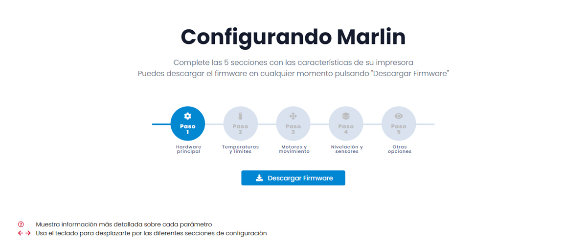
Basically, Marlin Builder consists of a Wizard (or configuration assistant) that will guide us through 5 sections. Each of these sections controls the basic parameters to compile a Marlin according to the mechanics and electronics. So when you have the 5 sections configured, you click to download firmware and you are ready. It sounds easy right?
Well, don’t be so happy as Marlin Builder doesn’t work miracles. If you configure something wrong, the compiler will show you an error. However, you can consult all the parameters in this article, and if you do not have previous experience, it is practically mandatory that you read it. Good luck with that!
Preparing our PC (necessary files)

The first thing you should do is prepare your PC to be able to compile the firmware (and edit it obviously). It will just be three easy steps, so let’s get to it:
Downloading the Marlin Firmware
Very simple, much like going to the official Marlin website, clicking on the section Download and search for the latest firmware available.
In this article we will use version 2.0.7.2 but new revisions and/or updates are published periodically, so choose the version you need. I recommend that you download the “Latest release” version, it is a link called “2.0.x.zip“.
After downloading it, unzip it into a folder on your computer’s desktop. Do not delete the compressed file, it can always help us to go back in our steps if we modify “too many things” within the firmware and we want to start from scratch again.
Text editor (Notepad, Sublime, Atom, etc.)
You will also need a good text editor. You can use the Arduino IDE interface, but I recommend using an editor oriented to programming.
These usually detect the programming structures and put different colors to the commands, variables, constants, etc. In such a way that they visually facilitate the compression of the code, something very welcome.
I personally use Sublime, since I started programming in PHP with this text editor. However you have multiple options such as Atom, Vim, VS Code, Notepad++ and many others. They all work very well, it is simply to adapt to the one you choose.
Download Arduino IDE (Option 1)
After modifying our Marlin firmware with your favorite editor, you must compile it before uploading it to the printer. To do this, you will use an integrated development environment, commonly called IDE, that Arduino offers completely free to the community.
Of course, we can download it from the arduino official website. To do this, you must access the Software->Downloads section, select Windows Installer (for example) and press the Just Download button to download it.
You can also make a contribution to the great development team behind Arduino. You just have to click on Contribute & Download and follow the instructions that will be shown on their website.
Download Visual Studio Code (Option 2)
As an alternative to the Arduino compiler, you can download and use Visual Studio Code, a software that I recommend since it includes a code editor and compiler all in one. And what’s more, if you need to download extra libraries for the firmware, it will manage it for you automatically.
Visual Studio Code can be downloaded for free from your web page. In fact some time ago I wrote a guide on how to configure it to compile Marlin firmwares, and that you have available at the following link: Configure and update your 3D printer using Visual Studio Code and Platform.io
“Configuration.h” file
As I mentioned before, there are 2 main files that manage everything when configuring Marlin 2.0.x. Of course, there are many more changes and modifications that we could make but for our current purpose they are not necessary at the moment (modifications of the original menu, logos, etc.)
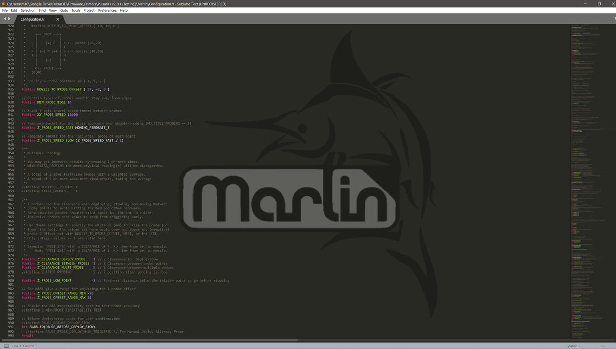
So we are going to start editing the Configuration.h file with the editor we have chosen (in my case Sublime), and we will follow in order the different most common options to take into account. Comment that this file contains the main hardware, language and driver settings, as well as settings for the most common features and components of our printer.
In white color, you can see the options that I have activated (or that are activated by default), and in dark gray the options that are deactivated. To activate an option we only have to eliminate the two bars “//” in front of the parameter in question. And to disable them otherwise, add them. If you are developer you will be familiar with this procedure.
In the case that we leave some parameter without reference due to the innumerable number of existing printers, do not hesitate to indicate it in the comments at the end of the article. In this way we will gradually complete all the information and it may be useful to more users.
Marlin logotype (SHOW_BOOTSCREEN)
It’s the Marlin logo that appears when the firmware boots. By default it appears active, we can deactivate it if we wish without any problem. It is not essential to configure Marlin 2 but we may even free up some memory.
You can also put your own logo or custom image, but we will explain that at the end of this guide in the section “Interesting tricks for Marlin“.
// Show the Marlin bootscreen on startup. ** ENABLE FOR PRODUCTION **
#define SHOW_BOOTSCREEN
Communication ports (SERIAL_PORT y SERIAL_PORT_2)
They are the communication ports of our electronics. In principle, the first one should not be modified unless you have some exotic electronics. The second I leave it disabled because I have an electronic MKS Gen v1.4 .
If your electronic board is a SKR V1.4 or SKR V1.4 Turbo you need activate SERIAL_PORT_2 and put the value -1 (as is by default). And for electronics SKR GTR V1.0 you must put the values -1 and 3 respectively in SERIAL_PORT and SERIAL_PORT_2.
These are certainly the electronics that I am most familiar with. For others you will have to search the values online, something that will not take you too long to locate.
/**
* Select the serial port on the board to use for communication with the host.
* This allows the connection of wireless adapters (for instance) to non-default port pins.
* Serial port -1 is the USB emulated serial port, if available.
* Note: The first serial port (-1 or 0) will always be used by the Arduino bootloader.
*
* :[-1, 0, 1, 2, 3, 4, 5, 6, 7]
*/
#define SERIAL_PORT 0

/**
* Select a secondary serial port on the board to use for communication with the host.
* :[-1, 0, 1, 2, 3, 4, 5, 6, 7]
*/
//#define SERIAL_PORT_2 -1
Communication speed (BAUDRATE)
Speed at which we will connect our computer to the printer, by default it is 250000 so we will leave it that way.
If by chance you have communication problems with your printer, you can lower the speed of this parameter to try to solve it.
/**
* This setting determines the communication speed of the printer.
*
* 250000 works in most cases, but you might try a lower speed if
* you commonly experience drop-outs during host printing.
* You may try up to 1000000 to speed up SD file transfer.
*
* :[2400, 9600, 19200, 38400, 57600, 115200, 250000, 500000, 1000000]
*/
#define BAUDRATE 250000
Motherboard or electronics (MOTHERBOARD)
Very important parameter. Here we will select the electronics that we have installed in our 3D printer. As there are many electronics available, we will have to find which one is ours and the value to place here.
You have a list of compatible electronics to use in the file “boards.h“. This is located in the following path of your Marlin firmware: \Marlin\src\core\boards.h
In my case, my 3D printer uses a MKS Gen v1.4 electronic boards. For it I must write “BOARD_MKS_GEN_13” as you can see in the example. You configure the one you have.
// Choose the name from boards.h that matches your setup
#ifndef MOTHERBOARD
#define MOTHERBOARD BOARD_MKS_GEN_13
#endif
Name of your machine (CUSTOM_MACHINE_NAME)
This is easy, the name you want your new configured printer to have. By default you will notice that it is disabled, hence these 2 bars appear “//” in front of #define.
We will remove the 2 bars and leave the configuration like this:
// Name displayed in the LCD "Ready" message and Info menu
#define CUSTOM_MACHINE_NAME "Pulsar X1 PRO"
Number of extruders (EXTRUDERS)
Here we are going to configure the number of extruders that our 3D printer has. By default, the initial value is 1, since most have an extruder. If this is not your case, enter the correct number of extruders.
// This defines the number of extruders
// :[1, 2, 3, 4, 5, 6, 7, 8]
#define EXTRUDERS 1
Filament diameter (DEFAULT_NOMINAL_FILAMENT_DIA)
In this section we will select the type of diameter that our printer uses. By default 3.0 comes, something strange since now most printers already usually operate at 1.75 in diameter. We will have to change it, very important 🙂
// Generally expected filament diameter (1.75, 2.85, 3.0, ...). Used for Volumetric, Filament Width Sensor, etc.
#define DEFAULT_NOMINAL_FILAMENT_DIA 1.75
Prusa Multimaterial Kit (PRUSA_MMU2)
Activate it if you have installed the original Josef Prusa multimaterial kit or some other chinese clon that are available in the market. If not, leave it as it is, with the two bars on.
/**
* Prusa Multi-Material Unit v2
*
* Requires NOZZLE_PARK_FEATURE to park print head in case MMU unit fails.
* Requires EXTRUDERS = 5
*
* For additional configuration see Configuration_adv.h
*/
//#define PRUSA_MMU2
Temperature sensors (TEMP_SENSORS)
In this section of the Marlin firmware we will define the existing temperature sensors in our 3D printer. In this latest version 2.0.7.2, has been added support for more extruders (with a total of 11 sensors supported), including a sensor for the chamber temp.
As you can see, there are a lot of them, and a list appears in the code itself. In the case that you do not have information about yours, try consulting Google as it will probably be documented by some other user with your same printer.
By default, only TEMP_SENSOR_0 is configured with value “1”. In my case, I must put the value “5” there.
As I also have a heated bed, to improve adhesion during printing and avoid Warping issues, I setup TEMP_SENSOR_BED with the value 1. I leave the rest at 0 since I don’t have any more extruders or a closed chamber at this printer.
/**
* --NORMAL IS 4.7kohm PULLUP!-- 1kohm pullup can be used on hotend sensor, using correct resistor and table
*
* Temperature sensors available:
*
*    -5 : PT100 / PT1000 with MAX31865 (only for sensors 0-1)
*    -3 : thermocouple with MAX31855 (only for sensors 0-1)
*    -2 : thermocouple with MAX6675 (only for sensors 0-1)
*    -4 : thermocouple with AD8495
*    -1 : thermocouple with AD595
*     0 : not used
*     1 : 100k thermistor - best choice for EPCOS 100k (4.7k pullup)
*   331 : (3.3V scaled thermistor 1 table)
*     2 : 200k thermistor - ATC Semitec 204GT-2 (4.7k pullup)
*     3 : Mendel-parts thermistor (4.7k pullup)
*     4 : 10k thermistor !! do not use it for a hotend. It gives bad resolution at high temp. !!
*     5 : 100K thermistor - ATC Semitec 104GT-2/104NT-4-R025H42G (Used in ParCan J-Head) (4.7k pullup)
*   501 : 100K Zonestar (Tronxy X3A) Thermistor
*   512 : 100k RPW-Ultra hotend thermistor (4.7k pullup)
*     6 : 100k EPCOS - Not as accurate as table 1 (created using a fluke thermocouple) (4.7k pullup)
*     7 : 100k Honeywell thermistor 135-104LAG-J01 (4.7k pullup)
*    71 : 100k Honeywell thermistor 135-104LAF-J01 (4.7k pullup)
*     8 : 100k 0603 SMD Vishay NTCS0603E3104FXT (4.7k pullup)
*     9 : 100k GE Sensing AL03006-58.2K-97-G1 (4.7k pullup)
*    10 : 100k RS thermistor 198-961 (4.7k pullup)
*    11 : 100k beta 3950 1% thermistor (4.7k pullup)
*    12 : 100k 0603 SMD Vishay NTCS0603E3104FXT (4.7k pullup) (calibrated for Makibox hot bed)
*    13 : 100k Hisens 3950  1% up to 300°C for hotend "All In ONE"
*    15 : 100k thermistor calibration for JGAurora A5 hotend
*    18 : ATC Semitec 204GT-2 (4.7k pullup) Dagoma.Fr - MKS_Base_DKU001327
*    20 : Pt100 with circuit in the Ultimainboard V2.x
*   201 : Pt100 with circuit in Overlord, similar to Ultimainboard V2.x
*    60 : 100k Maker's Tool Works Kapton Bed Thermistor beta=3950
*    61 : 100k Formbot / Vivedino 3950 350C thermistor 4.7k pullup
*    66 : 4.7M High Temperature thermistor from Dyze Design
*    67 : 450C thermistor from SliceEngineering
*    70 : the 100K thermistor found in the bq Hephestos 2
*    75 : 100k Generic Silicon Heat Pad with NTC 100K MGB18-104F39050L32 thermistor
*    99 : 100k thermistor with a 10K pull-up resistor (found on some Wanhao i3 machines)
*
*       1k ohm pullup tables - This is atypical, and requires changing out the 4.7k pullup for 1k.
*                              (but gives greater accuracy and more stable PID)
*    51 : 100k thermistor - EPCOS (1k pullup)
*    52 : 200k thermistor - ATC Semitec 204GT-2 (1k pullup)
*    55 : 100k thermistor - ATC Semitec 104GT-2 (Used in ParCan  J-Head) (1k pullup)
*
*  1047 : Pt1000 with 4k7 pullup
*  1010 : Pt1000 with 1k pullup (non standard)
*   147 : Pt100 with 4k7 pullup
*   110 : Pt100 with 1k pullup (non standard)
*
*  1000 : Custom - Specify parameters in Configuration_adv.h
*
*         Use these for Testing or Development purposes. NEVER for production machine.
*   998 : Dummy Table that ALWAYS reads 25°C or the temperature defined below.
*   999 : Dummy Table that ALWAYS reads 100°C or the temperature defined below.
*/
#define TEMP_SENSOR_0 5
#define TEMP_SENSOR_1 0
#define TEMP_SENSOR_2 0
#define TEMP_SENSOR_3 0
#define TEMP_SENSOR_4 0
#define TEMP_SENSOR_5 0
#define TEMP_SENSOR_6 0
#define TEMP_SENSOR_7 0
#define TEMP_SENSOR_BED 1
#define TEMP_SENSOR_PROBE 1
#define TEMP_SENSOR_CHAMBER 0
Temperature limiters (MINTEMP & MAXTEMP)
Configure in Marlin 2 these parameters is very important, since they control the maximum and minimum temperatures of our printer.
We will define in which ranges each and every one of the available sensors must be. In this way, if any sensor does not reach or exceed this temperature, Marlin emits an error on the display and deactivates the Hotend and the heated bed.
In my case I usually set the extruder temperatures at 5 degrees (minimum) and 265 degrees (maximum). In the event that an extruder or the bed does not reach 5º degrees, we will deduce that the Thermistor is not installed correctly, or is physically damaged.
In the same way, it will protect us in the event that the maximum temperature is accidentally exceeded, something crucial for our safety and that of our home.
// Below this temperature the heater will be switched off
// because it probably indicates a broken thermistor wire.
#define HEATER_0_MINTEMP 5
#define HEATER_1_MINTEMP 5
#define HEATER_2_MINTEMP 5
#define HEATER_3_MINTEMP 5
#define HEATER_4_MINTEMP 5
#define HEATER_5_MINTEMP 5
#define HEATER_6_MINTEMP 5
#define HEATER_7_MINTEMP 5
#define BED_MINTEMP 5

// Above this temperature the heater will be switched off.
// This can protect components from overheating, but NOT from shorts and failures.
// (Use MINTEMP for thermistor short/failure protection.)
#define HEATER_0_MAXTEMP 265
#define HEATER_1_MAXTEMP 265
#define HEATER_2_MAXTEMP 265
#define HEATER_3_MAXTEMP 265
#define HEATER_4_MAXTEMP 265
#define HEATER_5_MAXTEMP 265
#define HEATER_6_MAXTEMP 265
#define HEATER_7_MAXTEMP 265
#define BED_MAXTEMP 120
PID Tuning (Extruders)
Section that controls the settings of the algorithm that manages the temperature of the extruders and the heated bed.
We could go into more detail on how it works, but it is not the right article. If you are interested in learning more about PID Tuning I recommend that you take a look at the following article at REPRAP about Pid Tuning.
By default, some values are already predetermined for several of the best known printers on the market. Since my printer does not match the description, I have simply added my own values.
#if ENABLED(PIDTEMP)
//#define PID_EDIT_MENU         // Add PID editing to the "Advanced Settings" menu. (~700 bytes of PROGMEM)
//#define PID_AUTOTUNE_MENU     // Add PID auto-tuning to the "Advanced Settings" menu. (~250 bytes of PROGMEM)
//#define PID_PARAMS_PER_HOTEND // Uses separate PID parameters for each extruder (useful for mismatched extruders)
// Set/get with gcode: M301 E[extruder number, 0-2]

#if ENABLED(PID_PARAMS_PER_HOTEND)
// Specify between 1 and HOTENDS values per array.
// If fewer than EXTRUDER values are provided, the last element will be repeated.
#define DEFAULT_Kp_LIST {  22.20,  22.20 }
#define DEFAULT_Ki_LIST {   1.08,   1.08 }
#define DEFAULT_Kd_LIST { 114.00, 114.00 }
#else
#define DEFAULT_Kp  20.3    // Values that I added !!
#define DEFAULT_Ki  1.43    // Values that I added !!
#define DEFAULT_Kd  71.84   // Values that I added !!
#endif
#endif // PIDTEMP
To get the values from your printer, you can consult them on the Internet or you can make them yourself with an internal Marlin function called PID Autotune.
To do this, connect your printer to Repetier/Simplify3D or any other software that allows you to use Gcode commands. Once connected, send the command M303 E0 S200 C8 and the process will begin.
After heating and cooling the hotend 8 times, it will finish and display the following information. You only have to take the values of Kp, Ki and Kd and enter them in your firmware, in the fields DEFAULT_Kp, DEFAULT_Ki and DEFAULT_Kd.
bias: 92 d: 92 min: 196.56 max: 203.75
Ku: 32.59 Tu: 54.92
Clasic PID
Kp: 19.56
Ki: 0.71
Kd: 134.26
PID Autotune finished ! Place the Kp, Ki and Kd constants in the configuration.h
PID Bed Tuning (Heatbed)
The same as before, but for our heated bed. By default in the new firmware it will be disabled. If you have a heated bed, you must uncomment the #define PIDTEMPBED option as you will see in my configuration.
You can also run another internal Marlin function to get the optimal values for your bed. This is done with the Gcode command M303 E-1 C8 S90.
//===========================================================================
//====================== PID > Bed Temperature Control ======================
//===========================================================================

/**
* PID Bed Heating
*
* If this option is enabled set PID constants below.
* If this option is disabled, bang-bang will be used and BED_LIMIT_SWITCHING will enable hysteresis.
*
* The PID frequency will be the same as the extruder PWM.
* If PID_dT is the default, and correct for the hardware/configuration, that means 7.689Hz,
* which is fine for driving a square wave into a resistive load and does not significantly
* impact FET heating. This also works fine on a Fotek SSR-10DA Solid State Relay into a 250W
* heater. If your configuration is significantly different than this and you don't understand
* the issues involved, don't use bed PID until someone else verifies that your hardware works.
*/
#define PIDTEMPBED

//#define BED_LIMIT_SWITCHING

/**
* Max Bed Power
* Applies to all forms of bed control (PID, bang-bang, and bang-bang with hysteresis).
* When set to any value below 255, enables a form of PWM to the bed that acts like a divider
* so don't use it unless you are OK with PWM on your bed. (See the comment on enabling PIDTEMPBED)
*/
#define MAX_BED_POWER 255 // limits duty cycle to bed; 255=full current

if ENABLED(PIDTEMPBED)
//#define MIN_BED_POWER 0
//#define PID_BED_DEBUG // Sends debug data to the serial port.

//120V 250W silicone heater into 4mm borosilicate (MendelMax 1.5+)
//from FOPDT model - kp=.39 Tp=405 Tdead=66, Tc set to 79.2, aggressive factor of .15 (vs .1, 1, 10)
#define DEFAULT_bedKp 347.77
#define DEFAULT_bedKi 48.46
#define DEFAULT_bedKd 623.90

//120V 250W silicone heater into 4mm borosilicate (MendelMax 1.5+)
//from pidautotune
//#define DEFAULT_bedKp 97.1
//#define DEFAULT_bedKi 1.41
//#define DEFAULT_bedKd 1675.16

// FIND YOUR OWN: "M303 E-1 C8 S90" to run autotune on the bed at 90 degreesC for 8 cycles.
#endif // PIDTEMPBED
However, there are times when activating the PIDTEMPBED parameter is more damaging than not activating it. I recommend you not to enable it from the beginning.
Cold extrusion (PREVENT_COLD_EXTRUSION)
Both functions manage cold extrusion at Marlin. As we all know, it is not advisable to extrude filament if our Hotend is not turned on.
The option PREVENT_COLD_EXTRUSION it will directly prevent us from extruding material if our hotend does not reach the minimum temperature defined.
We can configure at what minimum temperature we will allow Marlin to extrude filament with the EXTRUDE_MINTEMP parameter. By default both are active, so you should not worry.
However, I have considered it important to name it so that you have proof that it exists.
/**
* Prevent extrusion if the temperature is below EXTRUDE_MINTEMP.
* Add M302 to set the minimum extrusion temperature and/or turn
* cold extrusion prevention on and off.
*
* *** IT IS HIGHLY RECOMMENDED TO LEAVE THIS OPTION ENABLED! ***
*/
#define PREVENT_COLD_EXTRUSION
#define EXTRUDE_MINTEMP 170
Extrusion lenght (PREVENT_LENGTHY_EXTRUDE)
As indicated in the comments, it prevents extrusion of filament from a distance greater than the one we have configured. This means that Marlin will only allow you to extrude a maximum of 200mm in a single GCODE command.
If you want to extrude much more than 200mm in a single command, for example in the case of having a function to load the filament from the display using Bowden, you will have to modify the parameter EXTRUDE_MAXLENGTH for a higher value. Both are enabled by default in Marlin 2.
If this is not your case, leave it as is. For example, in my case I insert the filament by hand so I have no need to modify it, but it is always good to know.
/**
* Prevent a single extrusion longer than EXTRUDE_MAXLENGTH.
* Note: For Bowden Extruders make this large enough to allow load/unload.
*/
#define PREVENT_LENGTHY_EXTRUDE
#define EXTRUDE_MAXLENGTH 200
Thermal protections (THERMAL_PROTECTION)
These three parameters activate the additional thermal protection that Marlin 2.0.x offers to prevent damage to our printers. They must always be active, in fact they come in Marlin 2 by default, so we will not touch them in any way.
/**
* Thermal Protection provides additional protection to your printer from damage
* and fire. Marlin always includes safe min and max temperature ranges which
* protect against a broken or disconnected thermistor wire.
*
* The issue: If a thermistor falls out, it will report the much lower
* temperature of the air in the room, and the the firmware will keep
* the heater on.
*
* If you get "Heating failed" errors the
* details can be tuned in Configuration_adv.h
*/

#define THERMAL_PROTECTION_HOTENDS // Enable thermal protection for all extruders
#define THERMAL_PROTECTION_BED     // Enable thermal protection for the heated bed
#define THERMAL_PROTECTION_CHAMBER // Enable thermal protection for the heated chamber
Mechanical parameters (COREXY kinematics)
There are different printers with different kinematics on the market. For example Cartesian kinematics, deltas, tripteron, corexy (and their variants), etc. The truth is that I would take one nice article to talk about all of them.
In the case that your 3D printer uses COREXY kinematics or any of its variants, you should activate its corresponding parameter. Since I have Cartesian kinematics, I leave everything disabled as you can see.
//===========================================================================
//============================= Mechanical Settings =========================
//===========================================================================

// @section machine

// Enable one of the options below for CoreXY, CoreXZ, or CoreYZ kinematics,
// either in the usual order or reversed
//#define COREXY
//#define COREXZ
//#define COREYZ
//#define COREYX
//#define COREZX
//#define COREZY
//#define MARKFORGED_XY  // MarkForged. See https://reprap.org/forum/read.php?152,504042
Endstop availables (USE_XMIN_PLUG & USE_XMAX_PLUG)
In this section we are going to indicate to our Marlin firmware the limit switches that we have connected to our motherboard. The most normal thing is to have 3 limit switches to indicate the minimum travels (or stops). In this way Marlin determines the initial position (0) in all axes when doing a HOMING.
Extra sensors can also be installed to determine the maximum travels. They will serve to prevent the machine from moving beyond what is strictly necessary. They are not essential, but they are a good option to have all the unforeseen under control.
In my particular case, I have two mechanical limit switches on the X axis (extruder) and on the Y axis (bed). And I also have a leveling sensor in Z, so I only leave the 3 minimun limit switches actived, as you can see for yourself in the following lines.
// Specify here all the endstop connectors that are connected to any endstop or probe.
// Almost all printers will be using one per axis. Probes will use one or more of the
// extra connectors. Leave undefined any used for non-endstop and non-probe purposes.
#define USE_XMIN_PLUG
#define USE_YMIN_PLUG
#define USE_ZMIN_PLUG
//#define USE_XMAX_PLUG
//#define USE_YMAX_PLUG
//#define USE_ZMAX_PLUG
Endstops logic (ENDSTOP_INVERTING)
Depending on the type of sensor or limit switch that we use, they will have a different logic. It has no greater mystery, just leave them all in FALSE, and if one of them does not work for you, change the logic here (you indicate TRUE).
In my particular case, X and Y I had to pass them to TRUE as you can see here:
// Mechanical endstop with COM to ground and NC to Signal uses "false" here (most common setup).
#define X_MIN_ENDSTOP_INVERTING true // Set to true to invert the logic of the endstop.
#define Y_MIN_ENDSTOP_INVERTING true // Set to true to invert the logic of the endstop.
#define Z_MIN_ENDSTOP_INVERTING false // Set to true to invert the logic of the endstop.
#define X_MAX_ENDSTOP_INVERTING false // Set to true to invert the logic of the endstop.
#define Y_MAX_ENDSTOP_INVERTING false // Set to true to invert the logic of the endstop.
#define Z_MAX_ENDSTOP_INVERTING false // Set to true to invert the logic of the endstop.
#define Z_MIN_PROBE_ENDSTOP_INVERTING false // Set to true to invert the logic of the probe.
Drivers configuration (DRIVER_TYPE)
Configuring the Marlin 2 firmware with the drivers that we have is something essential. But do not worry, it is a very simple process.
By default you will see that all the options are disabled, so you must enable the ones you are going to use, which will be where you have installed drivers on your board.
In my printer I have 3 motors in the 3 axes (X, Y, Z), and a single motor for the extruder. So I enable the necessary options. The first extruder is always named E0 as you can see.
But not only we must enable the option, but also indicate the driver that you have mounted on your electronics. Since I have DRV8825 , I have indicated it to the compiler, and that’s it.
In the comments you can see all the types of drivers available in Marlin 2, so locate yours and write it down as it appears.
/**
* Stepper Drivers
*
* These settings allow Marlin to tune stepper driver timing and enable advanced options for
* stepper drivers that support them. You may also override timing options in Configuration_adv.h.
*
* A4988 is assumed for unspecified drivers.
*
* Options: A4988, A5984, DRV8825, LV8729, L6470, L6474, POWERSTEP01,
*          TB6560, TB6600, TMC2100,
*          TMC2130, TMC2130_STANDALONE, TMC2160, TMC2160_STANDALONE,
*          TMC2208, TMC2208_STANDALONE, TMC2209, TMC2209_STANDALONE,
*          TMC26X,  TMC26X_STANDALONE,  TMC2660, TMC2660_STANDALONE,
*          TMC5130, TMC5130_STANDALONE, TMC5160, TMC5160_STANDALONE
* :['A4988', 'A5984', 'DRV8825', 'LV8729', 'L6470', 'L6474', 'POWERSTEP01', 'TB6560', 'TB6600', 'TMC2100', 'TMC2130', 'TMC2130_STANDALONE', 'TMC2160', 'TMC2160_STANDALONE', 'TMC2208', 'TMC2208_STANDALONE', 'TMC2209', 'TMC2209_STANDALONE', 'TMC26X', 'TMC26X_STANDALONE', 'TMC2660', 'TMC2660_STANDALONE', 'TMC5130', 'TMC5130_STANDALONE', 'TMC5160', 'TMC5160_STANDALONE']
*/
#define X_DRIVER_TYPE  DRV8825
#define Y_DRIVER_TYPE  DRV8825
#define Z_DRIVER_TYPE  DRV8825
//#define X2_DRIVER_TYPE A4988
//#define Y2_DRIVER_TYPE A4988
//#define Z2_DRIVER_TYPE A4988
//#define Z3_DRIVER_TYPE A4988
#define E0_DRIVER_TYPE DRV8825
//#define E1_DRIVER_TYPE A4988
//#define E2_DRIVER_TYPE A4988
//#define E3_DRIVER_TYPE A4988
//#define E4_DRIVER_TYPE A4988
//#define E5_DRIVER_TYPE A4988
//#define E6_DRIVER_TYPE A4988
//#define E7_DRIVER_TYPE A4988
Motor Steps configuration (DEFAULT_AXIS_STEPS_PER_UNIT)
In this section we will tell our printer how many steps will be carried out for each movement unit. Units may be defined in millimeters or inches.
In the case of using inches, you must activate the INCH_MODE_SUPPORT parameter. We are not going to activate that parameter, since we usually work with millimeters, and in this section we will introduce our steps for each of the axes and the extruder.
You first need to know the values to enter, so I recommend that you extract them from some firmware already available for your printer (to be safe).
Another option is to search for it on the Internet from some other user, browse forums, consult the manufacturer or, as a last option, calculate them yourself as you can see in this video.
/**
* Default Axis Steps Per Unit (steps/mm)
* Override with M92
*                                      X, Y, Z, E0 [, E1[, E2...]]
*/
#define DEFAULT_AXIS_STEPS_PER_UNIT   { 160, 160, 800, 803 }
Auto leveling sensor location (NOZZLE_TO_PROBE_OFFSET)
In the case that you use a self-leveling sensor (as is my case), you must indicate its position with respect to the nozzle to Marlin. This will necessarily be separated and we will define it as coordinates and in millimeters.
My level sensor is located 37mm to the right of the Nozzle, and 2mm further behind it, so the following configuration would remain:
/**
* Nozzle-to-Probe offsets { X, Y, Z }
*
* - Use a caliper or ruler to measure the distance from the tip of
*   the Nozzle to the center-point of the Probe in the X and Y axes.
* - For the Z offset use your best known value and adjust at runtime.
* - Probe Offsets can be tuned at runtime with 'M851', LCD menus, babystepping, etc.
*
* Assuming the typical work area orientation:
*  - Probe to RIGHT of the Nozzle has a Positive X offset
*  - Probe to LEFT  of the Nozzle has a Negative X offset
*  - Probe in BACK  of the Nozzle has a Positive Y offset
*  - Probe in FRONT of the Nozzle has a Negative Y offset
*
* Some examples:
*   #define NOZZLE_TO_PROBE_OFFSET { 10, 10, -1 }   // Example "1"
*   #define NOZZLE_TO_PROBE_OFFSET {-10,  5, -1 }   // Example "2"
*   #define NOZZLE_TO_PROBE_OFFSET {  5, -5, -1 }   // Example "3"
*   #define NOZZLE_TO_PROBE_OFFSET {-15,-10, -1 }   // Example "4"
*
*     +-- BACK ---+
*     |    [+]    |
*   L |        1  | R <-- Example "1" (right+,  back+)
*   E |  2        | I <-- Example "2" ( left-,  back+)
*   F |[-]  N  [+]| G <-- Nozzle
*   T |       3   | H <-- Example "3" (right+, front-)
*     | 4         | T <-- Example "4" ( left-, front-)
*     |    [-]    |
*     O-- FRONT --+
*/
#define NOZZLE_TO_PROBE_OFFSET { 37, 2, 0 }
Leveling speed (XY_PROBE_SPEED)
This parameter defines the speed that Marlin 2 will use when moving the auto level sensor between 2 measurement points. By default it comes in 133 * 60 mm/min, you can leave it by default or upload it, at your discretion.
// X and Y axis travel speed (mm/min) between probes
#define XY_PROBE_SPEED (133*60)
Reverse direction of motors (INVERT_X_DIR)
We will modify these parameters if when doing a HOME or when printing any part with our printer, any of the motors goes in the wrong direction. By default they are all configured with the FALSE option, but in my case I had to reverse the direction of my bed (Y axis) as you can see below.
However, another option is to invert the motor connection cable, so you can choose the more comfortable solution for you.
// Invert the stepper direction. Change (or reverse the motor connector) if an axis goes the wrong way.
#define INVERT_X_DIR false
#define INVERT_Y_DIR true
#define INVERT_Z_DIR false
Printing volume (X_BED_SIZE & Y_BED_SIZE)
We will define here the exact size of your Heatbed. My printer has a 285x206mm horizontal bed, so it would be configured this way:
// The size of the print bed
#define X_BED_SIZE 285
#define Y_BED_SIZE 206
Movement limits (MIN_POS & MAN_POS)
Once the size of our printing base (Heatbed) have been defined, we must configure Marlin 2 with the minimum and maximum limits of movement.
By default, for the minimums Marlin comes configured with the value 0, which we should not modify since it is HOME. For the maximum limits, Marlin directly uses the current size of our Heatbed in X and Y, which we had previously left configured in the previous parameter.
To finish with the configuration, in the Z axis the measure that we must add is the maximum printing height of your 3D Printer. In my particular case, I can print approximately 296mm, so I enter its value.
// Travel limits (mm) after homing, corresponding to endstop positions.
#define X_MIN_POS 0
#define Y_MIN_POS 0
#define Z_MIN_POS 0
#define X_MAX_POS X_BED_SIZE
#define Y_MAX_POS Y_BED_SIZE
#define Z_MAX_POS 296
Movement restrictions (MIN_SOFTWARE_ENDSTOPS)
For security reasons, and to avoid damaging the components of our printer, Marlin 2 comes by default configured so that we cannot exceed the minimum limits.
This means that when reaching a limit switch or sensor, it will not allow the engine to advance further even if you do it manually.
However, like many other things in Marlin 2.0.x, you can disable that limit if you wish. It is an option that I DO NOT RECOMMEND, but I wanted to comment on its existence.
I personally usually remove the limit on the Z axis. But as I have told you, unless it is essential or you know very well what you are doing, you must leave the values that the firmware brings by default.
// Min software endstops constrain movement within minimum coordinate bounds
#define MIN_SOFTWARE_ENDSTOPS
#if ENABLED(MIN_SOFTWARE_ENDSTOPS)
#define MIN_SOFTWARE_ENDSTOP_X
#define MIN_SOFTWARE_ENDSTOP_Y
#define MIN_SOFTWARE_ENDSTOP_Z
#endif
EEPROM storage (EEPROM_SETTINGS)
Marlin offers us the possibility to change the configuration of our printer from the display itself and then save the changes in the Eeprom.
If we want to have this possibility active, we must activate this parameter in our firmware.
#define EEPROM_SETTINGS // Persistent storage with M500 and M501
Pre-heating ABS/PLA (PREHEAT)
As you can see if you have already messed with your printer, Marlin offers you two initial options to pre-heat the printer prior to printing.
You can set the temperatures available for ABS and PLA filaments, although you could add more if you wish.
Something quite useful because the ones that come by default in the firmware can be improved. I personally leave these settings:
// Preheat Constants
#define PREHEAT_1_LABEL "PLA"
#define PREHEAT_1_TEMP_HOTEND 200
#define PREHEAT_1_TEMP_BED 60
#define PREHEAT_1_FAN_SPEED 0 // Value from 0 to 255

#define PREHEAT_2_LABEL "ABS"
#define PREHEAT_2_TEMP_HOTEND 250
#define PREHEAT_2_TEMP_BED 100
#define PREHEAT_2_FAN_SPEED 0 // Value from 0 to 255
Menu language (LCD_LANGUAGE)
Language that will appear in each and every one of the Marlin 2 firmware menus (display). At the moment, the one that convinces me the most is Spanish, so it is the one I have selected.
By default it comes English, so choose here what you need.
/**
* LCD LANGUAGE
*
* Select the language to display on the LCD. These languages are available:
*
*   en, an, bg, ca, cz, da, de, el, el_gr, es, eu, fi, fr, gl, hr, it, jp_kana,
*   ko_KR, nl, pl, pt, pt_br, ru, sk, tr, uk, vi, zh_CN, zh_TW, test
*
* :{ 'en':'English', 'an':'Aragonese', 'bg':'Bulgarian', 'ca':'Catalan', 'cz':'Czech', 'da':'Danish', 'de':'German', 'el':'Greek', 'el_gr':'Greek (Greece)', 'es':'Spanish', 'eu':'Basque-Euskera', 'fi':'Finnish', 'fr':'French', 'gl':'Galician', 'hr':'Croatian', 'it':'Italian', 'jp_kana':'Japanese', 'ko_KR':'Korean (South Korea)', 'nl':'Dutch', 'pl':'Polish', 'pt':'Portuguese', 'pt_br':'Portuguese (Brazilian)', 'ru':'Russian', 'sk':'Slovak', 'tr':'Turkish', 'uk':'Ukrainian', 'vi':'Vietnamese', 'zh_CN':'Chinese (Simplified)', 'zh_TW':'Chinese (Traditional)', 'test':'TEST' }
*/
#define LCD_LANGUAGE es
SD Card support (SDSUPPORT)
More than likely, it is essential to activate this option. It allows you to load the STL files using an SDCard.
Believe it or not, it is disabled by default in our Marlin firmware. You will need to activate it, as I have done in my firmware.
/**
* SD CARD
*
* SD Card support is disabled by default. If your controller has an SD slot,
* you must uncomment the following option or it won't work.
*
*/
#define SDSUPPORT
Simplify menus (SLIM_LCD_MENUS)
Marlin gives you the ability to navigate through countless menus from its display, to a point that is overwhelming (at least for me).
By the way, many of these parameters should have been previously configured in your firmware, without having to modify them “on the fly”.
To reduce the number of these menus, Marlin offers you the option of simplifying them with the SLIM_LCD_MENUS parameter. Not only will it simplify the menus, but you will save a not inconsiderable amount of memory. I recommend that you activate this option.
/**
* LCD Menu Items
*
* Disable all menus and only display the Status Screen, or
* just remove some extraneous menu items to recover space.
*/
//#define NO_LCD_MENUS
#define SLIM_LCD_MENUS
Display type (LCD / Controller Selection)
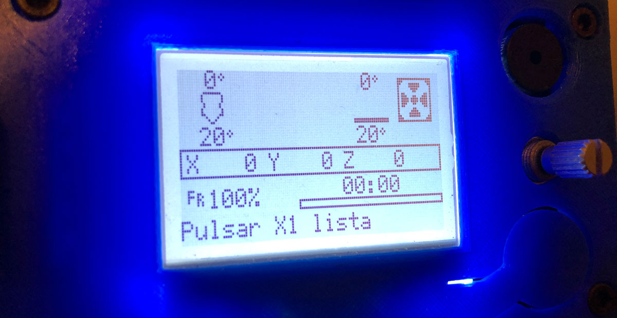
And finally, we have reached the display settings. If we take a close look at the Configuration.h file, we will see that there are countless displays.
It may seem a bit complicated, but really all we have to do is find the description of our LCD screen and uncomment in order to configure Marlin 2.
There are text-based displays, graphic LCD displays, OLED displays, and some more. I have one based on graphics called MKS MINI 12864 (pictured above). To do this, uncomment the following line.
If you cannot find the name of your screen, I recommend that you use the “Search” function of Windows, it is the fastest and easiest way.
//
// MKS MINI12864 with graphic controller and SD support
// https://reprap.org/wiki/MKS_MINI_12864
//
#define MKS_MINI_12864
A small detail to have in mind. In some cases (like mine), it is necessary to have external libraries to compile the firmware with support for our display. This is the case of the MKS MINI12864 display, you need to search and install them manually.
If you try to compile it, Marlin will give you an error, and it will tell you which library you need to install. For example, in my compilation it asks me for the U8glib library, let’s see the error:
sketch\src\HAL\HAL_AVR\u8g_com_HAL_AVR_sw_spi.cpp:65:10: fatal error: U8glib.h:
No such file or directory
The solution is very simple, we will go to the menu Tools->Manage libraries and we will make click on it. In the search box we will enter U8glib and press ENTER.
The online libraries available with this search parameter will appear and we will see that at the end there is ours “U8glib by Oliver”. Another click on the INSTALL button and solved.
Finally, the contrast setting of the display did not convince me too much, since it looked a bit dark at first, so I decided to change it.
You can modify the contrast (make the screen lighter/darker) from the display itself, but I prefer to leave it already set in the same firmware, since it is an option that I will not modify again, and in case I reset the EEPROM I won’t have to configure it again.
For this I had to edit a special file called “pins_RAMPS.h” located in the path \Marlin\src\pins\ramps\. Once edited, we will add the line #define LCD_CONTRAST 150 as we can see in the following lines:
#elif ENABLED(MINIPANEL)

#define BEEPER_PIN 42
// not connected to a pin
#define LCD_BACKLIGHT_PIN 65 // backlight LED on A11/D65

#define DOGLCD_A0 44
#define DOGLCD_CS 66

// GLCD features
// Uncomment screen orientation
//#define LCD_SCREEN_ROT_90
//#define LCD_SCREEN_ROT_180
//#define LCD_SCREEN_ROT_270

#define BTN_EN1 40
#define BTN_EN2 63
#define BTN_ENC 59

#define SD_DETECT_PIN 49
#define KILL_PIN 64
#define LCD_CONTRAST 150
Leveling the Heatbed (BED_LEVELING)
There are various methods or functions available in Marlin 2 to help us self-level our bed. By default they are deactivated in the firmware so we must activate them to be able to use them.
Explaining each and every one of them would give to write a complete article, so I will directly show you how to level the bed in two different ways. The first in the case that we do not have a leveling sensor installed and the second in the case that we do.
To begin, and in both cases, we must uncomment the AUTO_BED_LEVELING_BILINEAR function and then the RESTORE_LEVELING_AFTER_G28 function, so that they remain active in our firmware.
/**
* Choose one of the options below to enable G29 Bed Leveling. The parameters
* and behavior of G29 will change depending on your selection.
*
*  If using a Probe for Z Homing, enable Z_SAFE_HOMING also!
*
* - AUTO_BED_LEVELING_3POINT
*   Probe 3 arbitrary points on the bed (that aren't collinear)
*   You specify the XY coordinates of all 3 points.
*   The result is a single tilted plane. Best for a flat bed.
*
* - AUTO_BED_LEVELING_LINEAR
*   Probe several points in a grid.
*   You specify the rectangle and the density of sample points.
*   The result is a single tilted plane. Best for a flat bed.
*
* - AUTO_BED_LEVELING_BILINEAR
*   Probe several points in a grid.
*   You specify the rectangle and the density of sample points.
*   The result is a mesh, best for large or uneven beds.
*
* - AUTO_BED_LEVELING_UBL (Unified Bed Leveling)
*   A comprehensive bed leveling system combining the features and benefits
*   of other systems. UBL also includes integrated Mesh Generation, Mesh
*   Validation and Mesh Editing systems.
*
* - MESH_BED_LEVELING
*   Probe a grid manually
*   The result is a mesh, suitable for large or uneven beds. (See BILINEAR.)
*   For machines without a probe, Mesh Bed Leveling provides a method to perform
*   leveling in steps so you can manually adjust the Z height at each grid-point.
*   With an LCD controller the process is guided step-by-step.
*/
//#define AUTO_BED_LEVELING_3POINT
//#define AUTO_BED_LEVELING_LINEAR
#define AUTO_BED_LEVELING_BILINEAR
//#define AUTO_BED_LEVELING_UBL
//#define MESH_BED_LEVELING

/**
* Normally G28 leaves leveling disabled on completion. Enable
* this option to have G28 restore the prior leveling state.
*/
#define RESTORE_LEVELING_AFTER_G28
In this way, our sensor will go down at various points and create a virtual 3D mesh with the different heights. And since I always like to do the HOME in the center of the bed, I activate the option Z_SAFE_HOMING.
#define Z_SAFE_HOMING

#if ENABLED(Z_SAFE_HOMING)
#define Z_SAFE_HOMING_X_POINT ((X_BED_SIZE) / 2) // X point for Z homing when homing all axes (G28).
#define Z_SAFE_HOMING_Y_POINT ((Y_BED_SIZE) / 2) // Y point for Z homing when homing all axes (G28).
#endif
Once all this is configured, apply only the option you need for your firmware, option 1 without sensor or option 2 with sensor. Activating both is not necessary and can give you problems or compilation failures. Go for it…
Option 1: Sensorless configuration (4 corners)
This configuration is what we are going to apply if we do not have a leveling sensor in our print head. First we will indicate to Marlin 2 that we are going to perform the leveling without having said sensor.
/**
* The "Manual Probe" provides a means to do "Auto" Bed Leveling without a probe.
* Use G29 repeatedly, adjusting the Z height at each point with movement commands
* or (with LCD_BED_LEVELING) the LCD controller.
*/
#define PROBE_MANUALLY
//#define MANUAL_PROBE_START_Z 0.2
Then we will indicate how many test points (Probe points) we want our manual leveling to carry out, so we will modify the GRID_MAX_POINTS parameters. To level the 4 corners we will need 4 points, so we will leave the configuration in this way.
// Set the number of grid points per dimension.
#define GRID_MAX_POINTS_X 2
#define GRID_MAX_POINTS_Y GRID_MAX_POINTS_X
Last but not least, we will activate the LCD_BED_LEVELING and LEVEL_BED_CORNERS functions. This will create the appropriate menus on the display for this purpose.
/**
* Add a bed leveling sub-menu for ABL or MBL.
* Include a guided procedure if manual probing is enabled.
*/
#define LCD_BED_LEVELING

#if ENABLED(LCD_BED_LEVELING)
#define MESH_EDIT_Z_STEP 0.025 // (mm) Step size while manually probing Z axis.
#define LCD_PROBE_Z_RANGE 4 // (mm) Z Range centered on Z_MIN_POS for LCD Z adjustment
//#define MESH_EDIT_MENU // Add a menu to edit mesh points
#endif

// Add a menu item to move between bed corners for manual bed adjustment
#define LEVEL_BED_CORNERS
Option 2: Sensor setup (BABYSTEPPING)
This is the setting that I personally use on my printer with my level sensor on the head. In my case I used an infrared sensor, but it is applicable for any type of sensor (inductive, capacitive, IR, etc.)
If you have a BLTouch, I do recommend that you look for a more specific manual, since Marlin brings specific functions for it. Precisely in 3DWork we published a very complete article on how to configure it: Install and configure BLTouch/3DTouch in Marlin 2.0.x (MKS Gen, SKR, Anet A8, RAMPS)
Returning to our configuration, the first modification that we will make will be to indicate to Marlin that we have a fixed self-leveling sensor in our machine.
For this we will edit the following line and leave it like this:
/**
* A Fix-Mounted Probe either doesn't deploy or needs manual deployment.
*   (e.g., an inductive probe or a nozzle-based probe-switch.)
*/
#define FIX_MOUNTED_PROBE
Then we will configure how many test points (Probe points) we want our leveling with sensor to carry out, so we will modify the GRID_MAX_POINTS parameters.
I usually carry out 9 checkpoints before each print, so I leave the default options which are 3 per axis (3 x 3 = 9).
// Set the number of grid points per dimension.
#define GRID_MAX_POINTS_X 3
#define GRID_MAX_POINTS_Y GRID_MAX_POINTS_X
Then we must edit a new file called configuration_adv.h. It differs from the first basically in that it offers us more detailed customization options, add-ons and experimental or under development functions (such as BABYSTEPPING)
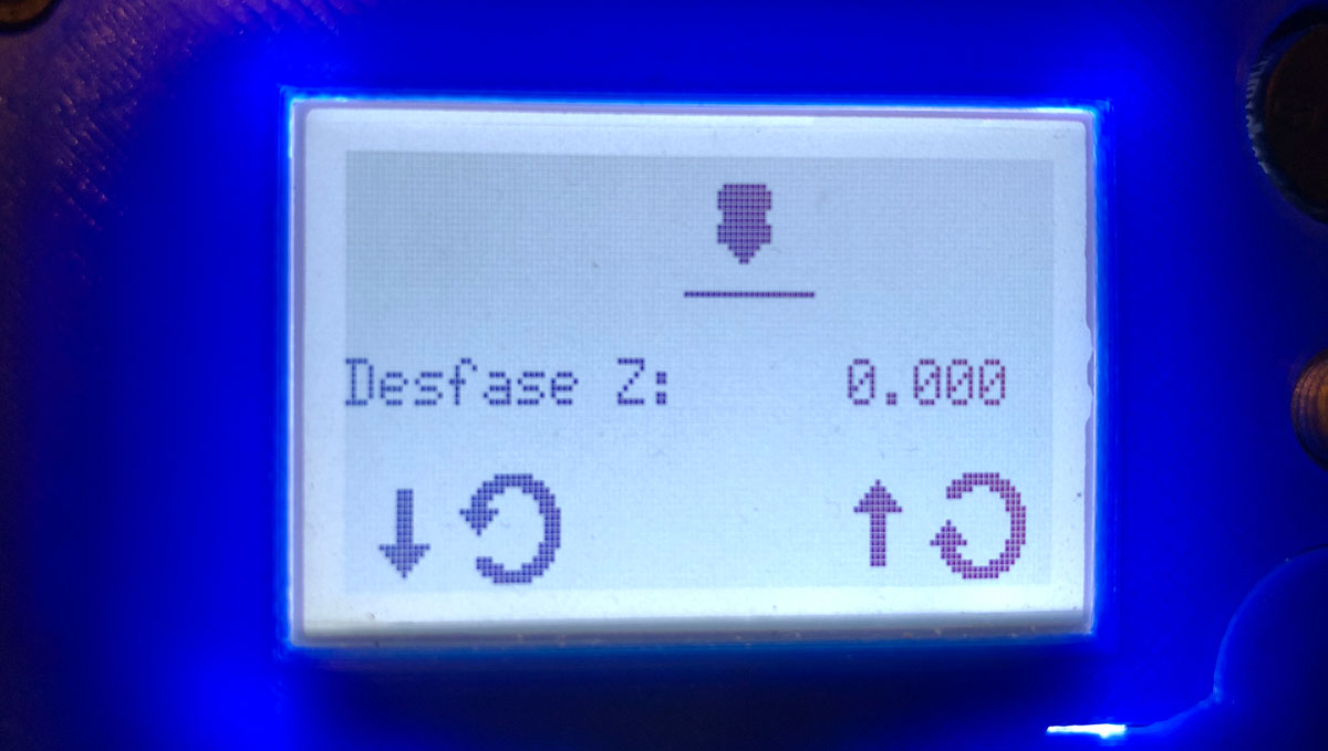
I use a leveling function available in Marlin 2 called BABYSTEPPING on my printer. This function allows me to calibrate with a sheet of paper the height of my leveling sensor in the center of the bed once.
Later, the printer will perform 9 test points (Probe Points) automatically at the beginning of each print. This way I won’t have to go corner by corner unnecessarily to calibrate my bed.
By default it is deactivated, so we will activate the BABYSTEPPING option as I show you below:
/**
* Babystepping enables movement of the axes by tiny increments without changing
* the current position values. This feature is used primarily to adjust the Z
* axis in the first layer of a print in real-time.
*
* Warning: Does not respect endstops!
*/
#define BABYSTEPPING
#if ENABLED(BABYSTEPPING)
//#define INTEGRATED_BABYSTEPPING         // EXPERIMENTAL integration of babystepping into the Stepper ISR
//#define BABYSTEP_WITHOUT_HOMING
#define BABYSTEP_ALWAYS_AVAILABLE         // Allow babystepping at all times (not just during movement).
//#define BABYSTEP_XY                     // Also enable X/Y Babystepping. Not supported on DELTA!
#define BABYSTEP_INVERT_Z false           // Change if Z babysteps should go the other way
//#define BABYSTEP_MILLIMETER_UNITS       // Specify BABYSTEP_MULTIPLICATOR_(XY|Z) in mm instead of micro-steps
#define BABYSTEP_MULTIPLICATOR_Z  20      // (steps or mm) Steps or millimeter distance for each Z babystep
#define BABYSTEP_MULTIPLICATOR_XY 1       // (steps or mm) Steps or millimeter distance for each XY babystep

#define DOUBLECLICK_FOR_Z_BABYSTEPPING    // Double-click on the Status Screen for Z Babystepping.
#if ENABLED(DOUBLECLICK_FOR_Z_BABYSTEPPING)
#define DOUBLECLICK_MAX_INTERVAL 1250   // Maximum interval between clicks, in milliseconds.
// Note: Extra time may be added to mitigate controller latency.
//#define MOVE_Z_WHEN_IDLE              // Jump to the move Z menu on doubleclick when printer is idle.
#if ENABLED(MOVE_Z_WHEN_IDLE)
#define MOVE_Z_IDLE_MULTIPLICATOR 1   // Multiply 1mm by this factor for the move step size.
#endif
#endif

//#define BABYSTEP_DISPLAY_TOTAL          // Display total babysteps since last G28

#define BABYSTEP_ZPROBE_OFFSET            // Combine M851 Z and Babystepping
#if ENABLED(BABYSTEP_ZPROBE_OFFSET)
//#define BABYSTEP_HOTEND_Z_OFFSET      // For multiple hotends, babystep relative Z offsets
#define BABYSTEP_ZPROBE_GFX_OVERLAY     // Enable graphical overlay on Z-offset editor
#endif
#endif
BONUS: Interesting Tricks for Marlin
Visualize your mesh in 3D
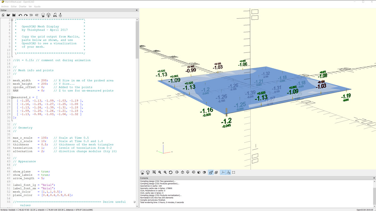
Since the new versions of Marlin appeared (2.0.x) it is possible to generate 3D meshes of our printing surface without the need to use Octoprint or any of its interesting plugins.
Marlin now provides you with a file that you can modify and load into Open SCAD to view our mesh at any time. You can read the full article at the following link: Visualize 3D mesh of our printing surface with Marlin 2.x (and without Octoprint)
Install games in Marlin
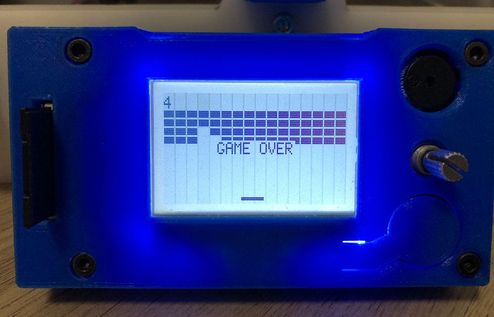
Another curious trick that Marlin offers us is to be able to activate a series of games hidden within its firmware. For this, it is necessary to have a graphic LCD screen, and modify some things within the firmware itself.
You have the complete article in the following link: Habilitando juegos ocultos en Marlin 2.0.x para tu impresora 3D
Custom logo in Marlin
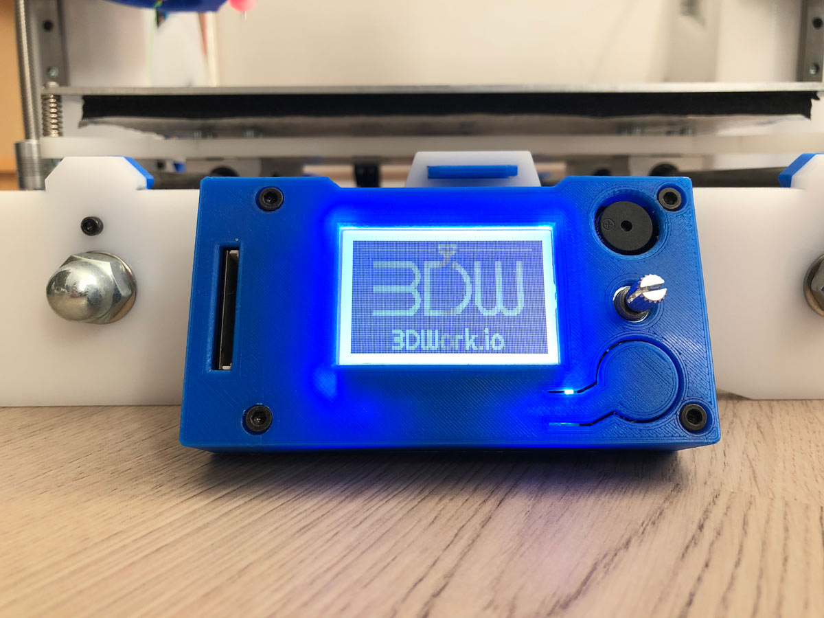
Since the release of Marlin firmware version 1.1.0 it is relatively easy to add custom logos to the Marlin firmware. As is logical, you need a graphic LCD screen, generate the logo and prepare the desired image.
Of course you will have to modify some things within the firmware itself. You can read the full article at the following link: Crea tu propio logotipo personalizado de inicio en Marlin 2.0.x
Marlin 2.0.x final build
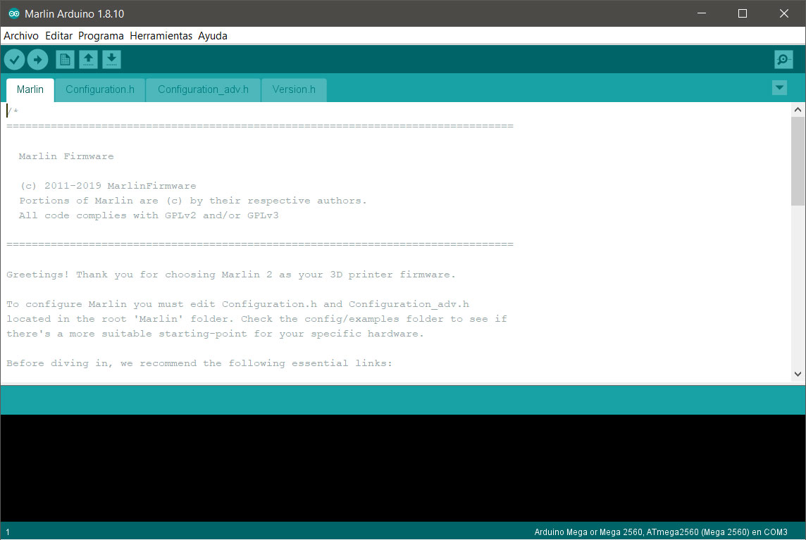
Well, it seems that it has cost but in the end we have reached this point. If everything is correct we should be able to compile our Marlin firmware without any problem. The first thing we must do in order to compile the firmware is to load it into the Arduino IDE, or into the Visual Studio Code.
If we use the Arduino IDE directly, we will open the folder where we had unzipped the firmware, we will go to the /Marlin folder and double click on the project file named Marlin.ino. This should load the entire project into the IDE.
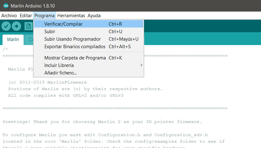
We basically have two options, one is verify/compile the firmware. This option will simply pre-compile the firmware and tell us if everything is configured correctly. The second option is upload the firmware, which will directly compile it and upload it to your printer.
Keep in mind that if you upload the firmware, you must have previously configured the arduino IDE and connected your printer via USB to your computer. If it does not detect your printer board, after compilation it will give an error and will not upload the firmware.
So, at this point, we are going to limit ourselves simply to giving the option to verify/compile the firmware, and once we see that it compiles everything correctly, we will go to the next step that will be the final one, upload the firmware to our machine.
To do this we will go to the menu Program -> Verify/Compile or press the hot keys Ctrl + R.
Uploading Marlin to your printer
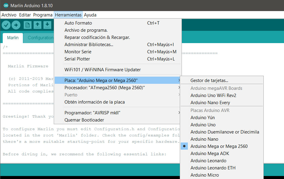
As we mentioned in the previous section, before we can upload the finished firmware to our printer, we must configure the Arduino IDE. We will go to the Tools menu and configure these 3 sections:
- Board: Select the type of electronic board of your printer
- Processor: ATMega 2560 or ATMega 1280
- Port: A COM port will appear, select it manually
If we have selected everything correctly, we should not have a major problem. To upload it we will definitely go to Program > Upload or press the hot keys Ctrl + U.
Build Marlin firmwares with Visual Studio Code and Platform.io (Recommended)
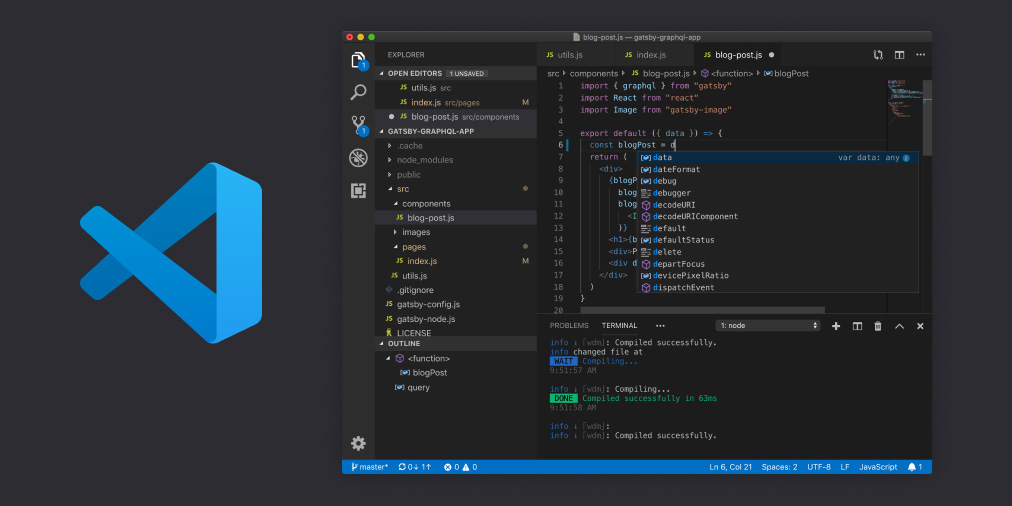
In the case that you have a 32-bit electronic board, I strongly recommend using Visual Studio Code and its Platform.io extension. This is a light, powerfull and totally free code editor + pluging for compile Marlin firmwares.
You also have a great article on our website where step by step is explained how to do it, I leave you here the direct link: Configure and update your 3D printer using Visual Studio Code and Platform.io
Final remarks
I hope and wish that the article Setting up Marlin 2.0.x from scratch could be of help to you. However, as I mentioned at the beginning, it is not intended to be a specific user manual, but a simple introduction to it using my current printer as an example.
Although, the idea is to complete the article day by day with much more information. I do not rule out that you may experience something unforeseen when configuring Marlin 2.0.x for your printer.
If that is the case, I would appreciate it if you would share it with us in the comments or directly in our Telegram channel.
And finally, if there is any typo in the article, I apologize in advance. Setting up Marlin 2.0.x as you can see is quite laborious (which is not the same as difficult). And it is completely feasible that some parameter has been overlooked (nothing easier than correcting it in a later edition). Feel free to notify me at the end in the comments.
Good luck!
Feel free to read other interesting articles in 3DWork:
- Complete guide SKR v1.4 / v1.4 Turbo with TMC2209 Sensorless drivers and Display TFT35 V3.0
- To buy a 3D printer: Essential guide to buy your first 3D printer in 2021
- BIQU H2 Extruder (Review): One of the lightest and most compact extrusion system on the market
- Expiration date in filaments. Utopia or something that we should demand from all manufacturers?
- QIDI TECH X-Plus: Industrial-grade, high-performance 3D printing for your desktop
- Phrozen Shuffle XL Lite: Large-scale printing, with 2K resolution and ParaLED technology
- SKR GTR V1.0: Complete analysis and configuration with TMC22xx drivers and Sensorless
- Adding filament sensor in SKR electronics (MINI E3, v1.3, v1.4 and v1.4 Turbo)














Thank you so much for putting this together. Im just a hobbyist and this article really helped explain Marlin better for me. I found it very informative and detailed. I look forward to learning more as I go and it’s thanks to people such as yourself, that I’m able to do these projects.