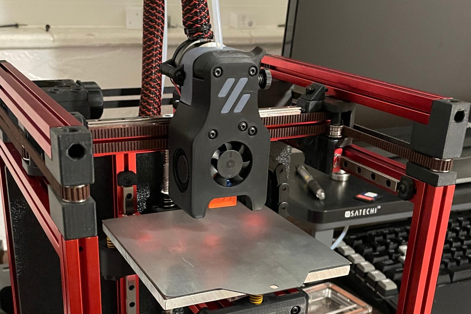
The Voron 0.1 Kit FYSETC is a very peculiar DIY 3D printer and today at 3DWork we will talk a little about its functionality and some of its features.
It should be noted that the Voron 0.1, despite its size and appearance, is not a toy since basically we are going to have the same characteristics that we have in printers of medium/high range in a very small format.
Brief introduction
It is important to emphasize that despite the excellent design work of Voron, its documentation and that FYSETC in its kit provides us with everything necessary for its correct assembly, the process it is labor intensive and it is advisable to have some experience building 3D printers as well as electronics and Klipper.
On the other hand, once mounted, its behavior is a real delight with the only “but” of its reduced print size. Being ideal as a second high-performance printer especially for printing technical materials or as a portable printer that can always have interesting applications.
And before continuing with today’s article, remember that you can find us on our social networks or join our Telegram channel. Either way we will be eternally grateful. Let’s get down to business then…
Where can I buy the Voron 0.1?
As we always do, we leave you some links where you can purchase the FYSETC kit for this printer, as well as some components.
If you use them, the price of the product will be the same as if you access it normally, but 3DWork will have a small commission. Something that will help us support the project and be able to continue offering this kind of articles.
You can also use our 3D printing product search engine developed by 3DWork, where with a single search you will be shown prices from different marketplaces (Amazon, Aliexpress, Banggood, etc.)
Contents of the FYSETC Kit
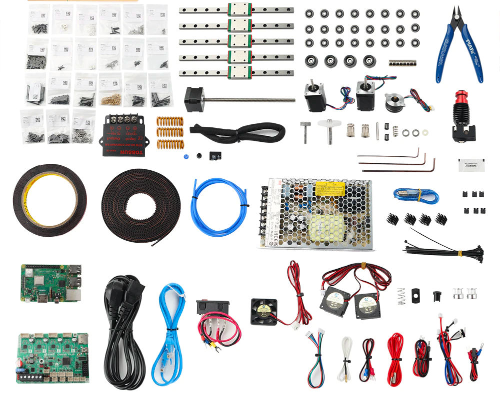
As we have previously mentioned, FYSETC has done an enormous job with this kit, including everything necessary to start, except for the printed parts, which we can purchase in other kits.
Soon we will have a metal kit that is probably highly recommended, even if we already have our Voron 0.1 assembled.
The whole kit comes perfectly packaged and labeled, just as an improvement it would be ideal to label the aluminum profiles to know how to easily identify each one of them.
Below you can see an image of the components of the kit, a list of them and a description of the most outstanding components.

As you can see, in the electronics section we have a correct FYSETC Cheetah v1.2b, although in newer kits this has been updated on FYSETC Cheetah v2.0 (kit rev1.1).
This board come with a STM32 MCU and TMC2209 drivers. It also includes a Raspberry Pi 3B+ which, together with the Klipper system, will allow us high-speed printing, remote printer control (via WiFi or Ethernet), a camera for visualize our printer, accelerometers, 12864 LCD screens, etc.
Too, it is included a powerful 50W power supply (considering the size of our printer), as well as a DCDC 5V 10A module for the specific power supply of our Raspberry Pi 3B+, although we could use it to power led strips or other peripherals.
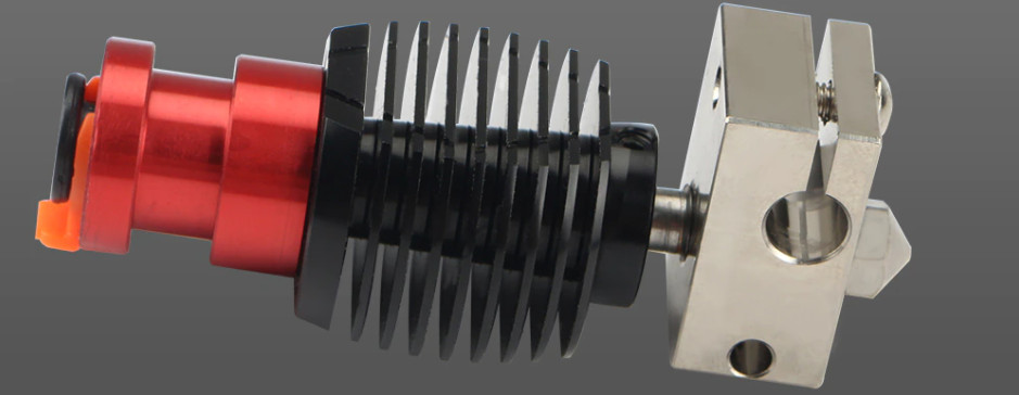
As for the included Tornado hotend, it is compatible with Dragon systems, being able to work with high temperature components. And of course, with the wiring ready to be able to connect all the components in a comfortable and simple way, something that is greatly appreciated in this machine.

The linear guides are quite correct, which will give us great precision and reliability in the movements of the Voron 0.1.
The mic6 aluminum heated bed is perfectly machined, and together with the 24V 75W heater with temperature protection (thermofuse) and the magnetic PEI, they offer a round finish.
In addition, the 3-point manual leveling system will allow us to have a perfect printing surface. Finally, highlight the engines included which, despite not having the Voron/LDO serigraphy, have behaved in our tests exceptionally and without any type of problem.
Printer mounting
As we have already commented, and we will continue to do so throughout the article, the Voron 0.1 is not an easy printer to assemble given its complexity of CoreXY kinematics packed into a small chassis.
So we advise to have information about it before starting its assembly. Here we leave you some links and a video that we hope will be useful to you:
- FYSETC Voron 0.1 Github repository: We will be able to find firmware, documentation and parts to print adjusted to the assembly kit.
- Parts to help in the assembly that we can find here and here
- Manual assembly Voron 0.1
To facilitate the assembly process, here is a video of the hotend assembly to give you some idea of the steps in a more visual way and as an extra help to the Voron assembly manual.
Electronics
Below we show you the connection diagram of all the electronics, always depending on which kit version we have:
Firmware
The Voron 0.1 printer is initially designed for Klipper, although if it is a system with which you do not feel comfortable it is always feasible to make it work on Marlin.
We are not going to explain in detail how to assemble the entire system since we have them in detail in the guides that we have shown you. We will only be giving you the steps to start it with links to more detailed guides.
- Klipper installation, you can find it at Klipper installation guide detailed information about it. In any case, and for our Voron 0.1, we have used MainsailOS as an image for our Raspberry Pi with Klipper and proceeded, for convenience to manage the Klipper components, to install Kiauh.
- Create our Klipper firmware, back to our Klipper installation guide we can find how to generate it.
We will use the following configuration to generate our Klipper firmware for our Cheetah v1.2:

To upload the firmware you must use the following command (connected via SSH):
1stm32flash -w out/klipper.bin -v -i rts,-dtr,dtr /dev/ttyUSB0
You can find more information on how to upload your firmware here.
We will use the following configuration to generate our Klipper firmware for our Cheetah v2.0:

You can find more information on how to upload your firmware here.
- Obtain the ID of our MCU to configure it in Klipper, once we have our electronics completely updated with the Klipper firmware we must obtain the ID of our MCU. You have more details of the process here.
- Configuring our printer.cfg, now that we have our on-board firmware ready and the Klipper system mounted, all we have to do is access our Mainsail/Fluidd interface and start configuring our printer.cfg. In this case we have the examples for the rev1.0 kit and for the rev1.1kit.
Start-up
Now that we have our machine assembled and the control system ready, we can start with the start-up by making a series of previous adjustments, the initial calibration of the machine and, of course, the configuration of our favorite slicer or laminator.
Mainsail… Klipper interface
Given that to carry out some of the previous checks/adjustments and later the management of the printer, we will show you some interesting parts of Mainsail, which is the web interface from where we will control our printer.

Terminal, depending on the configuration of our Mainsail or version, this will appear as a tab or a widget in some of the sections. From it we can send commands to our printer.

Control, in this module we can make movements of our axes, modify the feedrate, make home or know the coordinates of our nozzle.
Pre-adjustments and checks
- Belt tensioning. In adjusting the belt tensioning for printers with CoreXY kinematics it is vital that both belts moving the X and Y axis have a similar tension.
- Motor directions. To check that the motors are in the correct direction, and with the printer off, we will manually position the print head in the center of the bed and then send the command/macro SET_CENTER_KINEMATIC_POSITION from the console. Then we can use Fluidd’s motion controls to verify that each axis moves in the correct direction. In the event that the address is not correct, we must indicate it with a ! (or remove it) in the engine’s dir_pin definition. [stepper_y] dir_pin: !y_dir_pin # Add ! in front of pin name to reverse Y stepper direction
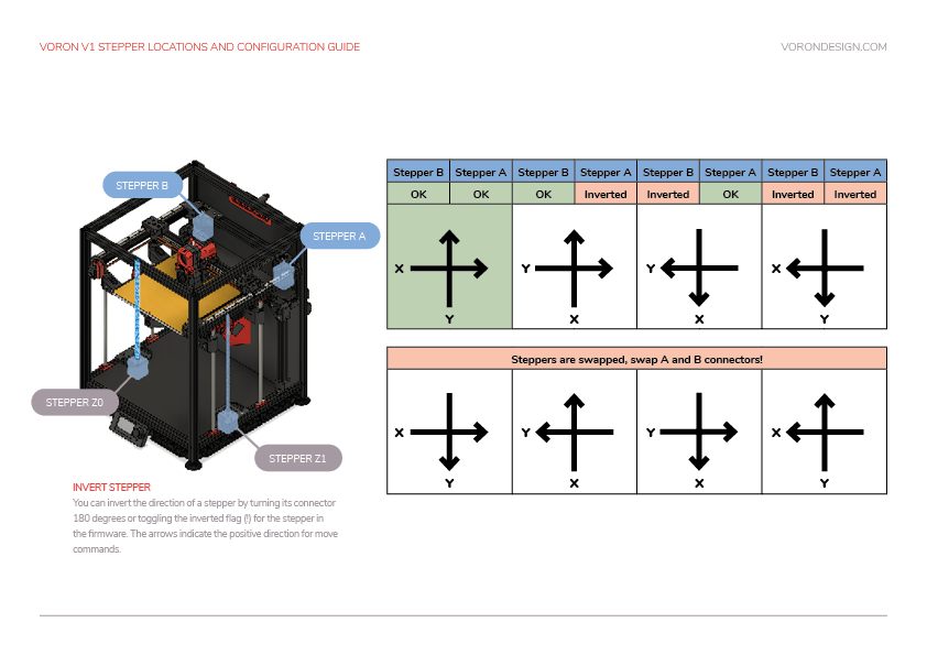
- Endstops: Once we have verified that the direction of our motors is correct, we will have to check our endstops.
- Physical endstops, in the case of using physical limit switches we can check its status from the Fluidd interface itself in the Tunning tab. The correct state is OPEN without being activated and TRIGGERED activated
- Sensorless, if we choose to use sensorless we will have to adjust the sensitivity inside the printer.cfg file adding an override of the configuration default: [tmc2209 stepper_x] driver_SGTHRS: 70 # Stall guard threshold, this is your X sensitivity, to adjust, copy this section and override it in printer.cfg.[tmc2209 stepper_y] driver_SGTHRS: 70 # Stall guard threshold, this is your Y sensitivity, to adjust, copy this section and override it in printer.cfg.
- Z-Probe, if we have a leveling sensor depending of the type that we use the verification of the same can vary. In the case of inductive/capacitive/IR devices, which usually function as physical limit switches, they are checked in the same way. On the other hand BLTouch/3DTouch or similar style sensors, which use a servo part, have to be verified differently using the commands BLTOUCH_DEBUG COMMAND=pin_down to display the pin, a BLTOUCH_DEBUG COMMAND=touch_mode and verifying with QUERY_PROBE having to return a probe: open . We will use the BLTOUCH_DEBUG COMMAND=pin_up command to bring the pin back up. In the event that something does not work correctly and the sensor is left hanging, flashing red, we will return it to normal using BLTOUCH_DEBUG COMMAND=reset.
- Z-Offset, in the case of using a leveling sensor we must adjust the Z-Offset, which is the distance between when the sensor is activated when detecting the bed and the nozzle, for this we will use the command PROBE_CALIBRATE to enter the calibration. Once the positioning process is finished, we will use the traditional folio and the commands TESTZ Z=-.1 (we can vary the value to our liking) to adjust Z until the folio have friction with the nozzle. When we have the appropriate value we will use the command ACCEPT which will save the value obtained in our printer.cfg, this is found in the lower zone of values that are auto-generated and not it must be modified: #*# [probe]#*# z_offset = 1.4 If we want to adjust it manually we can modify that value.
Calibration
We already have the machine ready to continue with the important initial adjustments to be made before starting with the calibration.
PID-tune
The PID adjustment is an important point to perform during start-up and whenever we modify any part/component related to the heating system of our machine. The process is very simple and it is done very quickly, so we have no excuse to do it whenever we see abnormal temperature fluctuations:
- Hotend/Extruder, we will launch the PID_CALIBRATE command from the terminal, for example: PID_CALIBRATE HEATER=extruder TARGET=200. Once finished we will SAVE_CONFIG so that it is saved in our printer.cfg < /em>our PID configuration.
- Bed, in this case we will launch the command as follows: PID_CALIBRATE HEATER=heater_bed TARGET=60 Once finished we will do SAVE_CONFIG so that it is saved in our printer.cfg our PID settings.
Extruder calibration (e-steps)
Before starting to print, we will have to calibrate the steps of our extruder.
- With the hotend at the optimum temperature for the material we are using we will make a mark 120mm from the extruder inlet.
- From Mainsail in Control we will extrude 50mm twice (to make a total of 100mm extruded) we do it twice because by default Klipper has limited the maximum extrusion distance which on the other hand we can adjust if we wish.
- After extruding we will measure from the entrance of the extruder, where we previously took as a reference to mark the 120mm, up to the mark we made in the first point. And with that value we will perform the following formula (we will assume that, although in a perfect world that distance should measure 20mm, we have obtained 19mm):
120mm-19mm= 101mm - Now we will calculate our new rotation_distance in the extruder part of our printer.cfg using the value of the following formula:
current_rotationdistance_value*(actual_valueextrudedpreviousstep/value_requestedtoextrudeinpreviousstep)= newrotationdistance_value
As an example: 4.63 * (101/100) = 4.58
Bed leveling
In the FYSETC configuration files for your Kit Voron 0.1 We have startup macros to perform manual bed leveling. In any case, we provide you with the link to the Klipper documentation on bed leveling bed to customize or explore other options if we deem it appropriate.
Pressure Advance
Pressure Advance is another interesting Klipper feature that also has similar features in other firmwares. Pressure Advance allows us total control over extrusion avoiding artifacts such as threads or filament remains in movements without extrusion or improving the finish in changes of direction in our parts.
The process to measure our Pressure Advance value using a test tower designed to highlight these flaws and follow the procedure described in the following link.


Resonance-compensation… Input Shaping
One of the great features of Klipper, and that we will soon see in other firmwares such as Marlin or Duet, is support for Input Shaping which is a technique that allows vibrations to be reduced (ringing, echoin, ghosting, rippling are other names for such artifacts).
This type of artifacts are produced by mechanical vibrations normally caused by sudden movements in changes of directions. Something normally caused by… a chassis that is not sufficiently rigid, belts that are too tight or too little, alignment problems in parts of the chassis or kinematics, movements of large masses in the axes of movement, etc.
So it is advisable before starting to make sure that we have tried to solve as much as possible the most common issues mentioned.
Given that it is a very extensive process, we are going to explain the two ways to be able to adjust Input Shaping, providing links to the official documentation, reminding you that in our case we use a sensor to measure the resonances of our machine:
- Manual resonance compensation, in this case and through a test tower we can find and adjust the Input Shaping values by following the instructions in the previous link.
- Resonance compensation using an accelerometer, in our case when using it on other machines we opted to use an ADXL345 accelerometer for automatic measurement of resonances that you can find the process in the previous link. The process is a bit laborious in the installation of certain software components and requires extra wiring, but based on the results obtained, we believe it is worth it.
Slicer/laminator configuration
FYSETC has in its repository for Voron 0.1 profiles for PrusaSlicer and SuperSlicer. We can download the following file VoronV0.ini and export the settings on these laminators. Something that will save us huge amounts of time in tests and that is appreciated.
Experience of use
The Voron 0.1 is an impressive printer, despite its toy-like appearance, and it wouldn’t be fair to rate it for its print volume. We are talking about a 3D printer for medium/advanced users with some experience or wanting to learn how to handle machines that go beyond the current standard of Cartesian/Marlin printers.
Thanks to the documentation, design of printed parts and qualities in the components, the assembly and handling of the printer is relatively simple, always bearing in mind that it is an advanced printer.
Being able to manage the machine from any device thanks to Klipper, our LCD screen or even using a screen on our Raspberry Pi is a delight.
Once assembled, the basic machine/firmware settings and the calibrations of our slicer have been made, we can affirm that the quality and reliability of the printer has been superb in all the tests and trials carried out.
Voron 0.1 Do I really need it?
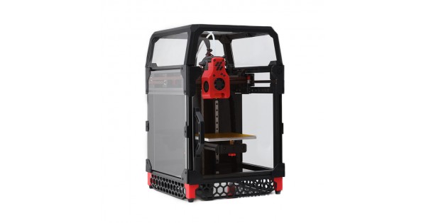
As we have previously commented, the Voron 0.1 is a very peculiar printer. We have a high-performance printer condensed in a small chassis with a reduced printing area (120mmx120mmx120mm)
And this certainly isn’t something we’re used to. But on the other hand it is a perfect printer for various functions:
- Excellent for small parts, especially if we use very technical materials
- High-precision and high-speed printer (less printing times)
- Completely portable and low consumption
- Closed design that improves and allows you to work with almost any technical material
- Access to a number of mods and its extensive Voron
In the event that all these advantages coincide with what we are looking for and the cost of the machine is within our budget, it is one of the best printers that we can have today with these characteristics.
Because let’s not fool ourselves, it has a high cost but equals the benefits it offers.
Final valuation
Although we have a lot of experience in building 3D printers, whether they are commercial, DIY or designed/manufactured by ourselves, we must be honest and emphasize that the assembly of the Voron 0.1 is not easy.
And that is why good planning, prior documentation of the process and most importantly… arming yourself with patience and being meticulous in each of the steps to follow will help us a lot in our endeavor.
On the other hand, once you have assembled the Voron 0.1 and start the adjustments, you realize that it is not a normal printer and its possibilities multiply with use. In addition, there is a large Voron community that continually improves and adds features.
This makes the Voron 0.1 a printer to be reckoned with. Of course, for a very specific use given its size limitations.
As always FYSETC has done an excellent job on their kit, being able to simplify the assembly process. Note the following:
- A hotend that surprised us with its behavior, although ideally if we are going to work continuously with technical materials it would be one of the points to improve without no doubt
- The whole set and parts of the kinematics are of good quality, as are the profiles used
- The motors, despite not being original LDOs from Fysetc, indicate that they are identical but silk-screened with your brand
Not related to FYSETC kit, since it is not included in it, it is important to emphasize that it is necessary to print enough parts and that these, depending on what materials we intend to work with, should be printed in PETG, although the ideal is the use of ABS/ASA.
In any case it is very important that the printer we use to print these parts is very well calibrated since the tolerances of these parts, given the size of the printer, is very low and can give us real headaches during assembly, adjustment or use of our Voron 0.1.
And that’s all my friends. If you have reached the end, there is nothing left but to thank you for your interest in our articles. We hope and wish that it has been to your liking and interest.
Other interesting articles on 3DWork.io:
- Slice Engineering Mosquito: A Spectacular Hotend for High-Performance 3D Printers
- SKR MINI E3 V3: Analysis and complete guide of this new electronic board revision
- Ratrig VCore3: Review, guide and configuration of a DIY printer that touch the perfection
- BTT Octopus Pro: Natural evolution of Octopus for high performance and speed machines
- The best resin 3D printers in 2021
- Longer LK5 Pro: Review of a High-Volume Desktop 3D Printer
- Nozzle: Learn all the basics about this essential component
- Elegoo Mars 2 Pro: Review of a great resin printer for home use
- BTT Octopus: Analysis and Setup Guide with Marlin and Klipper
- FYSETC S6: Complete guide to this excellent electronic board for our 3D printers
- BTT SKR 2: How to detect and repair the failure of the first revisions (REV A)














Déjanos un comentario