Cartesian 3D printers “Prusa style” have always been the most widespread when it comes to desktop. There are many models available on the market, and new ones are constantly appearing to join the current catalog.
However, if you are crazy about 3D printing like us, I have no doubt that you will always look for the best machine for personal or professional use.
And certainly it could be said that machines with a “cube” format and with CoreXY / H-Bot kinematics are the most suitable (and extended) for these tasks.
In the next article we will talk about a very interesting model that we hope will be to your liking. Remind you as always, that we have a great community in our Telegram. So if you want to be part of it, have no doubts in join us.
Brief introduction
Today in 3DWork we will show you the Ratrig VCore3, one of the best 3D printers that have fallen into our hands at the chassis, kinematics, support and community level. Which ensures us a total success in our choice for our new machine.
It is important to mention that this type of machine, unlike other normally low-mid-range commercial machines, does not come assembled and we must plan their assembly well.
Although we anticipate in advance that Ratrig has done an incredible job in preparing his kit and documentation of the assembly process, where not a single detail is missing.
Ratrig VCore3 Printer
Why do we say that the Ratrig VCore3 printer is one of the best choices when it comes to kits? Let’s go with a little history about it.
Ratrig started with his version VCore in 2017 and since then there have been different revisions trying to apply all the improvements based on feedback from the community and the incredible work of Pawel Kucmus, who is one of the most prolific members and has contributed the most to the VCore platform.
Some of the new features introduced in this latest version are the following:
- 3-point kinematics system for the printing bed: It allows us to automatically level it. In addition, the 3-point clamping system helps to substantially improve the bed compared to other more traditional 2-point systems, video below.
- CoreXY kinematics with 9mm belts: Offers incredible robustness to this type of machine. In addition, Ratrig again did an exceptional job in the placement of the brackets and the design of the support pieces.
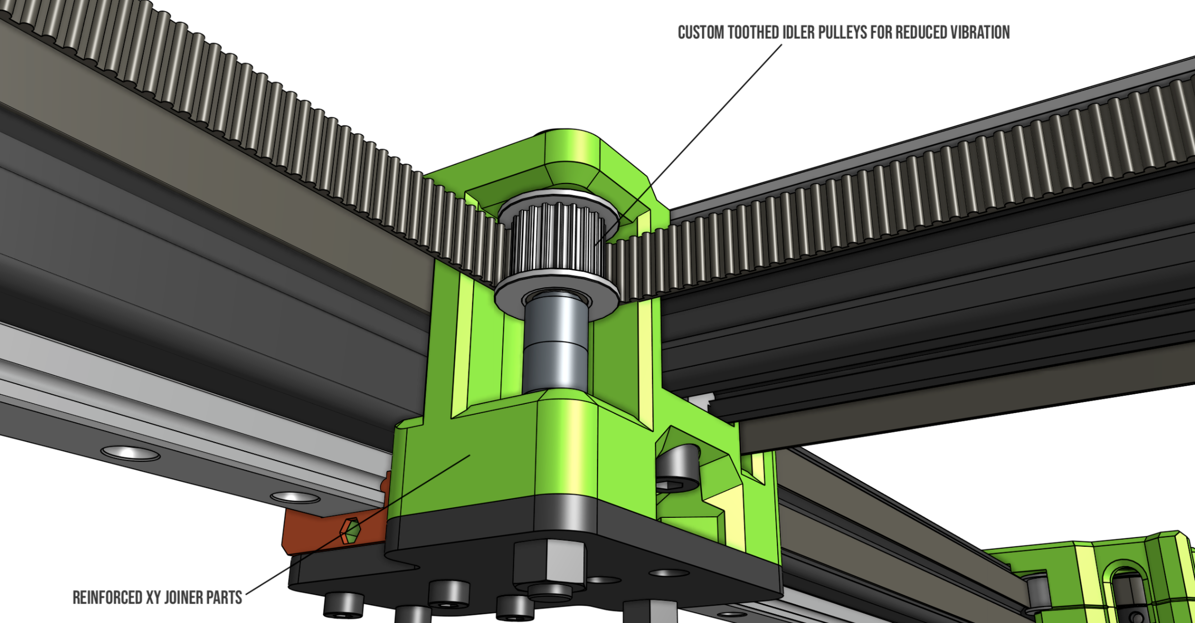
- Use of linear guides in all axes: Improving consistency, linearity and smoothness in movements even at high speeds..
- One of the most robust chassis we have seen in these types of kits with the use of 3030 aluminum profiles.
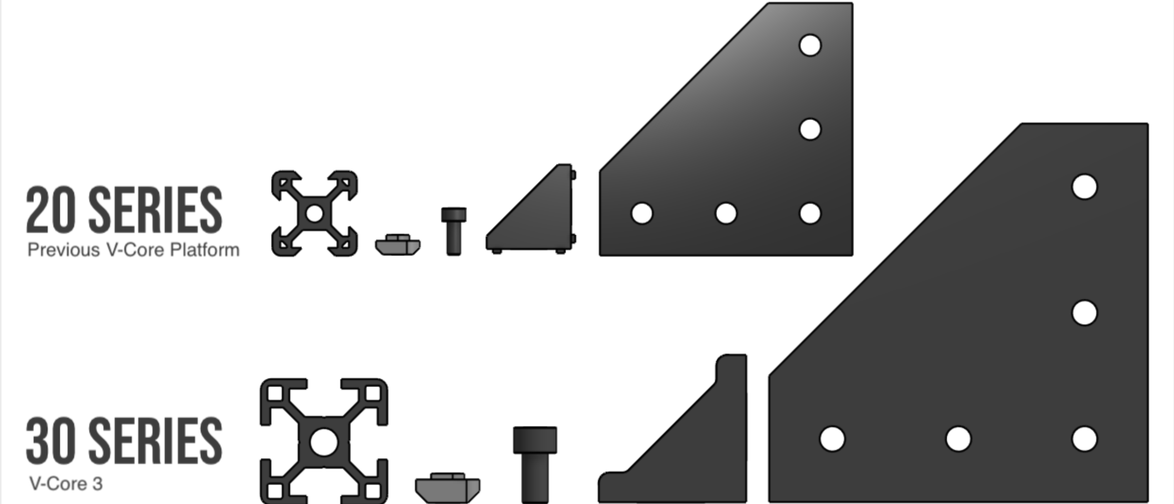
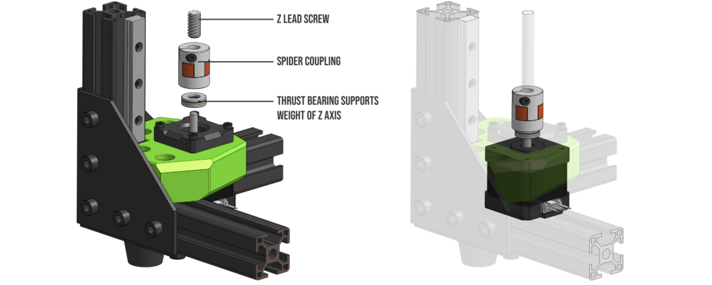
- Improved system in the Z axis couplings to avoid artifacts in our prints
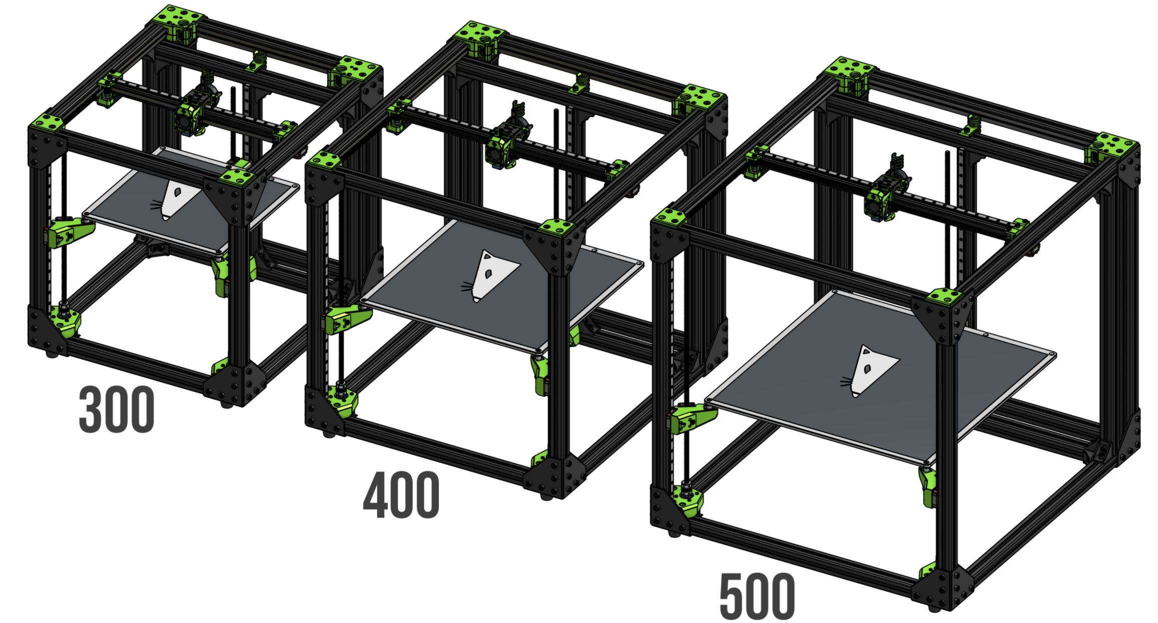
- 3 versions in print size available… 300, 400 and 500 mm3
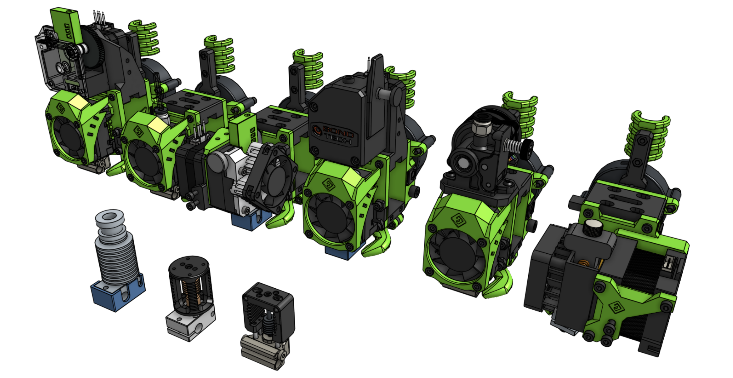
- Use the EVA 2.x print head system: From our point of view, one of the most advanced heads for DIY printers with linear guides. In addition to having unmatched compatibility with hotend systems, extruders and leveling systems. And if that’s not all, it looks perfect on our machine.
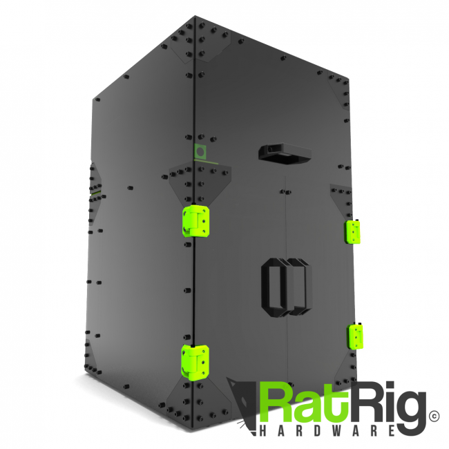
- Prepared to work technical materials with enclosure options for the printing area. Something vital depending on which filaments such as ABS, Nylon, etc.
Where to buy the Ratrig VCore 3?
The VCore3 is a Ratrig design polished during its different versions until it reaches the current model on the market.
You can get the kit in his web page, where you can customize the size and components to suit your needs. This gives us extreme flexibility that we have not found in other similar printer kits.
Ratrig also makes available the BOM (list of materials) with everything necessary to assemble the machine ourselves, something that is appreciated if you want to venture yourself in the whole process.
Kit contents
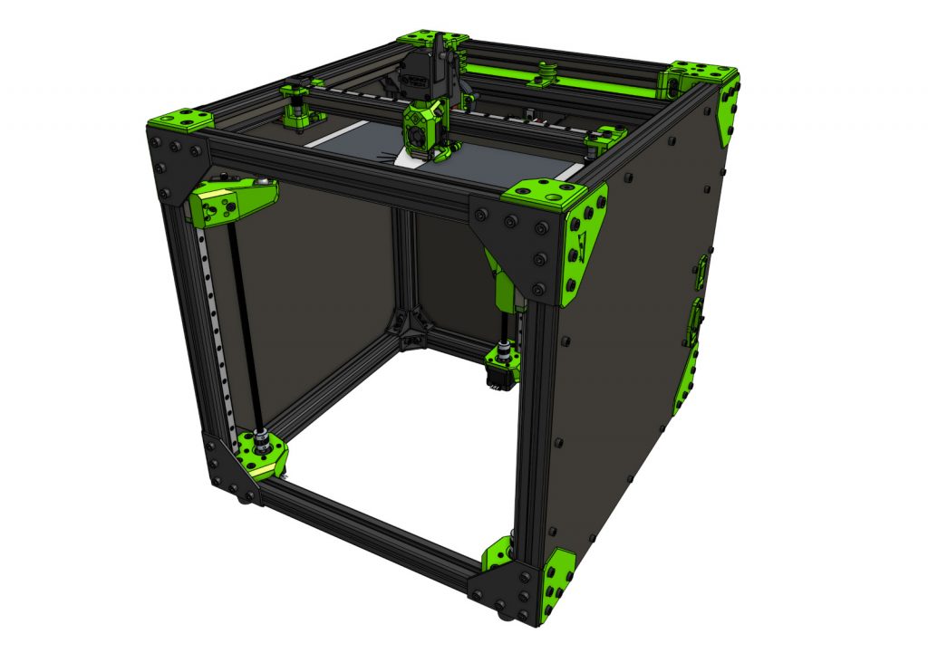
One of the great advantages of Ratrig is that we can assemble the kit that they offer to our measure being able to choose between different alternatives to build our kit Ratrig or use other components that better suit our needs.
In any case it is advisable to try to combine these components in such a way that they are compatible or supported by the default configurations are supported since it simplifies us a lot the assembly process.
3DWork Configuration
In our case we select the following components to assemble our VCore3 : < td> Engines
| Kit Chasis | Ratrig VCore3 300×300 |
| Electrónica | BigTreeTech SKR Octopus v1.1 Drivers TMC2209 UART Raspberry Pi 4 |
| Hotend/Extrusor | Dragon Hotend v2 / Orbiter |
| Motores | StepperOnline 1.8 |
| Cama | Cama Keenovo 750W Prima PEI SSR |
| Sensor de nivelación | PINDAv2 |
| Firmware | Klipper – VCoreOS |
| Filamento partes impresas | Fiberlogy e-PETG Verde Transparente |
Assembling the Ratrig VCore3
If you are used to commercial machines, I must warn you that the process of assembling a kit or DIY (do it yourself) printer can be frustrating and laborious. Everything will depend on the disposition, time and patience you have.
It should be noted that Ratrig has once again done an excellent job with a comprehensive and detailed step-by-step guide to fully assemble the printer. Of course, we advise you that between 6 and 8 hours are dedicated to the complete assembly.
However, it is always a great opportunity to fully learn how your 3D printer is assembled and how the components can be disassembled for later repairs without any fear.
Printed parts
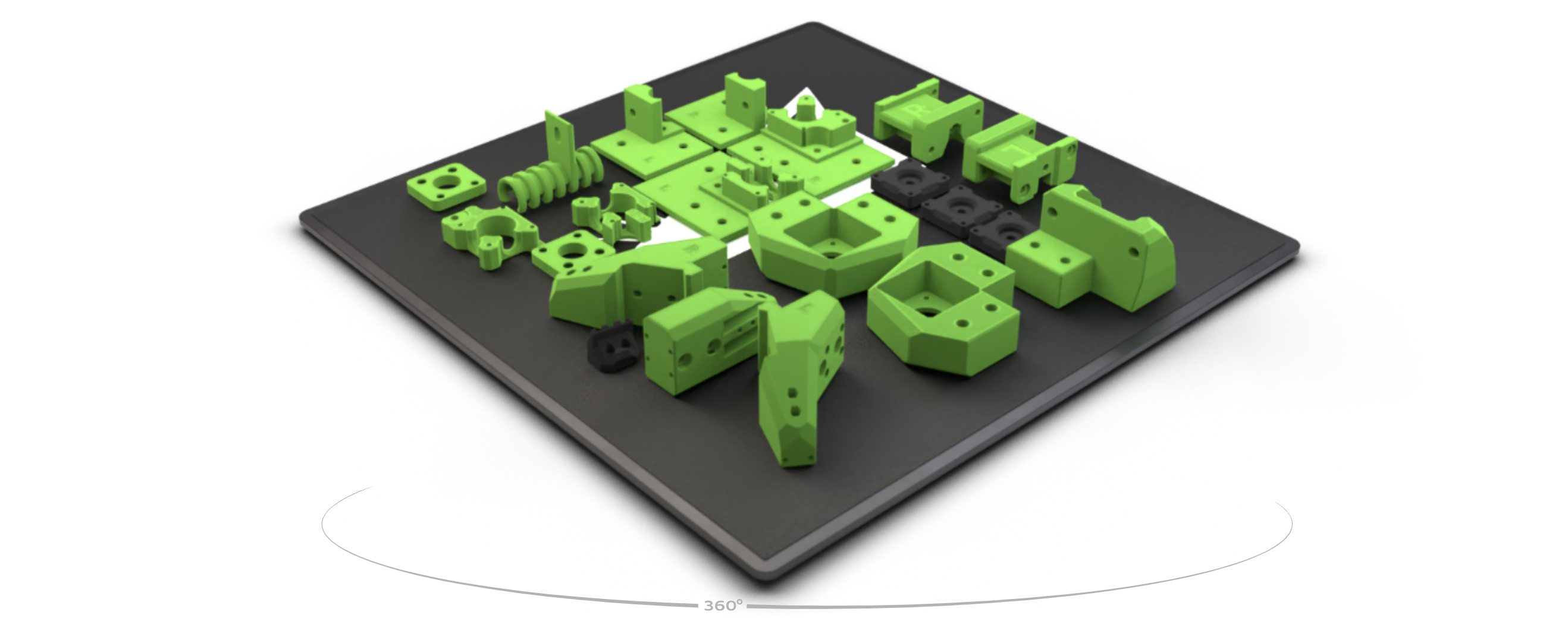
Before starting with the assembly of the chassis it is advisable to have the basic kit of printed parts that you can get updated in your repository, or by downloading directly from the following file ZIP.
Ratrig offers full access to the entire design in CAD format using Onshape, which will allow us to modify these parts to adjust them to our needs if necessary.
In addition, they suggest different options to print the pieces. We advise you to make them in PETG, ASA or ABS. In our case we print them in Fiberlogy ePETG color Translucent Green and Onyx which, apart from giving it great rigidity, looks great.
| CONFIGURATION | VALUES |
| Perimeters | 4 x 0.45 mm |
| Layer height | 0.2 – 0.3 mm |
| Filler | Gyroid 10% / Rectilinear 25 % |
| Supports | Usually not necessary |
Chassis
The basic kit includes everything necessary for the assembly of the chassis which, with the detailed documentation and labeling of the necessary hardware, greatly simplifies the process.
In any case, we advise you to first print the essential kit from the previous point, as well as the installation / centering tool for linear guides and have a square.
Here you can find the detailed guide step by step, as well as a video that will also help in the assembly process and that we put below.
Electronics
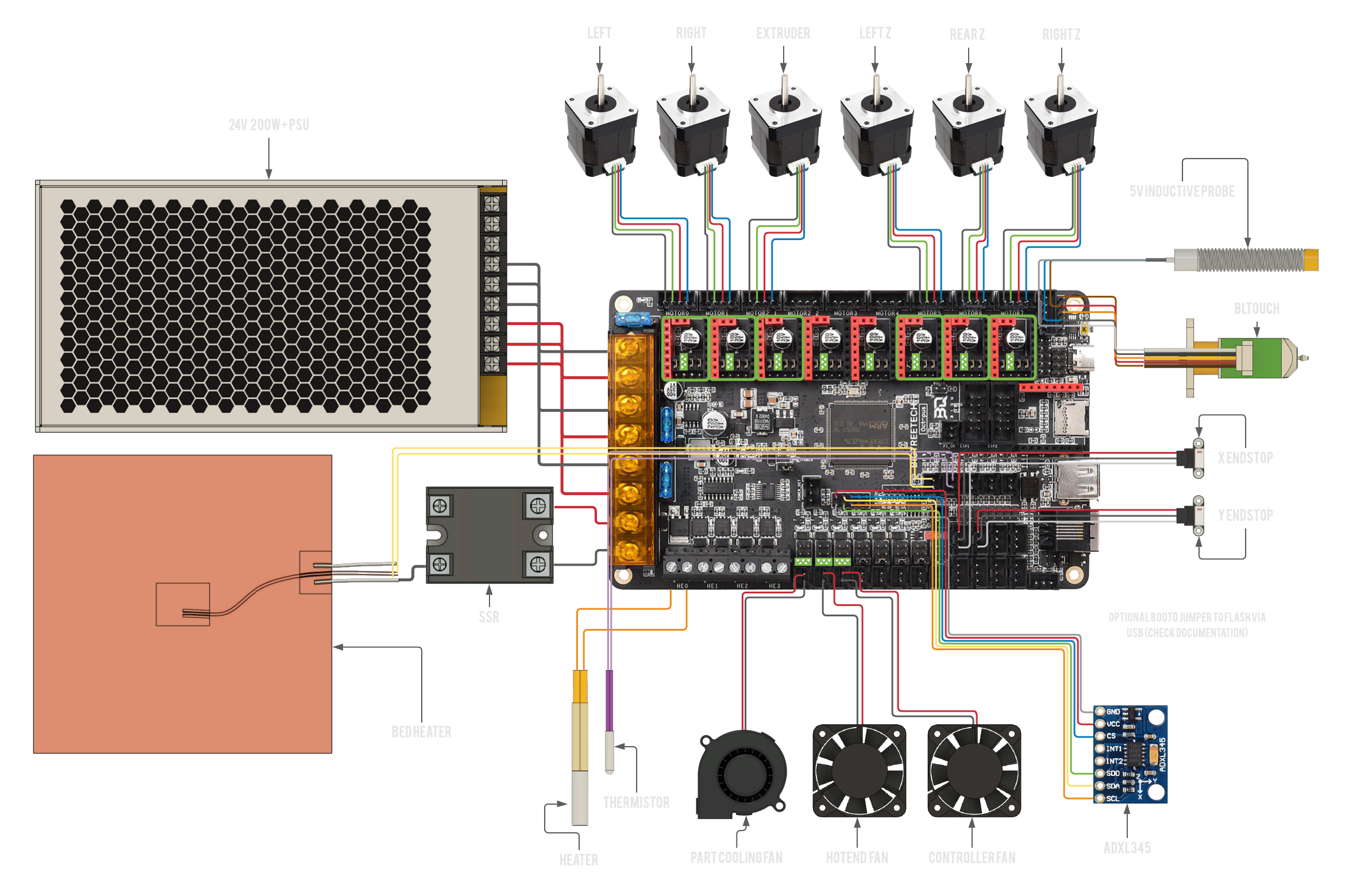
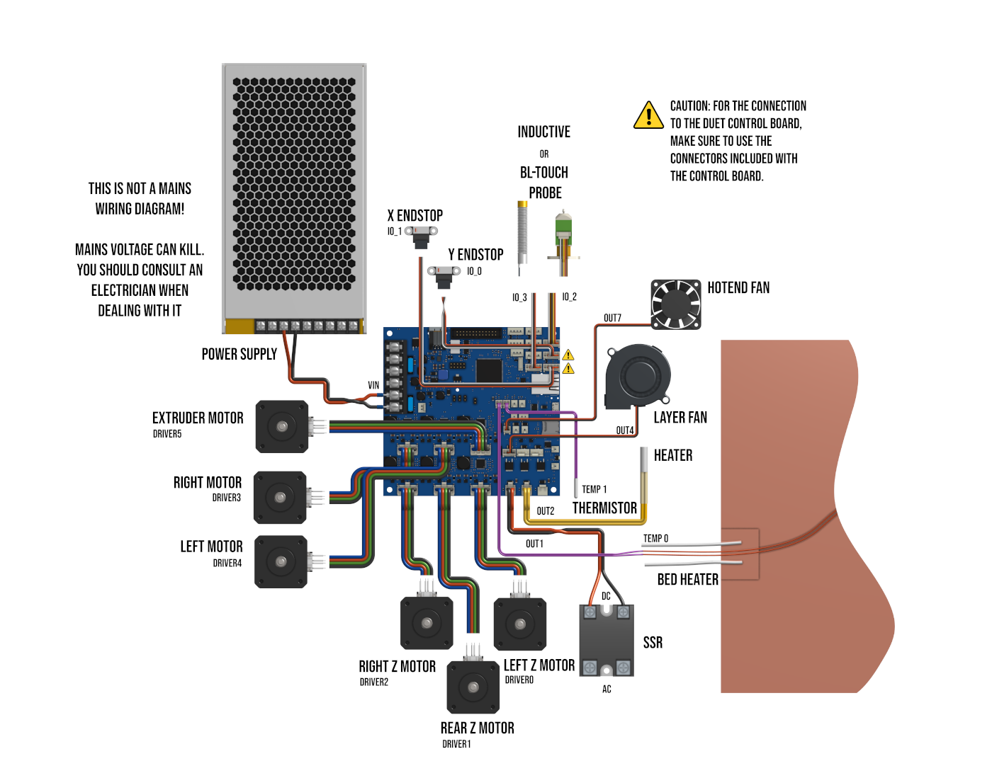
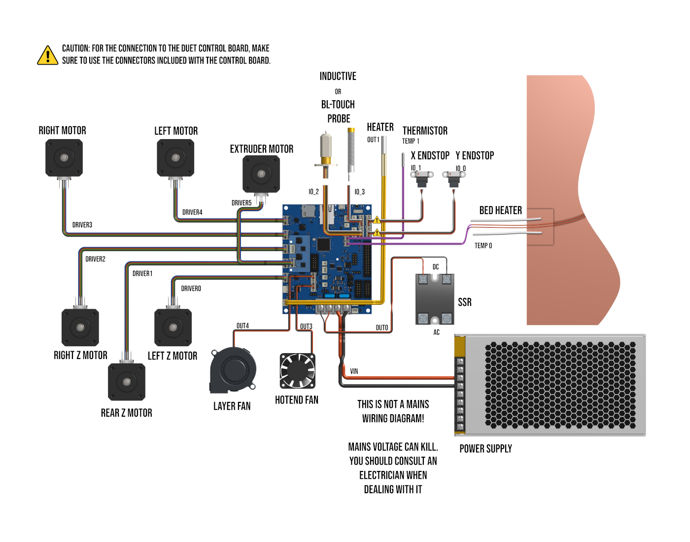
Once the mechanical part is finished, we are going to begin with the installation and configuration of the electronics and wiring of our Ratrig VCore 3. We leave you the necessary diagrams below, click on the image to enlarge.
In our case we will use an electronic BTT Octopus, along with drivers TMC2209 in UART mode and we will choose to use sensorless to simplify wiring and make our printer as clean as possible of cables. On the other hand, we will use the excellent Stepper Online together with the Dragon hotend and the Orbiter extruder, in addition of a PINDAv2 leveling sensor and a 750W AC silicone bed.
Firmware
How could it be otherwise, Ratrig has rounded up this VCore3 with exceptional support for the two firmwares that best suit this type of machine.
Duet – Reprap Firmware
One of the firmwares with direct support from Ratrig is Duet / Reprap Firmware, since Duet electronics are the electronic ones that support the VCore3 .
In the following link you can find all the configuration of the main files to adjust said firmware to our VCore3. You can also find them in the following ZIP.
VCoreOS … Klipper
The second firmware with direct support is Klipper, but in this In case they have created their fully custom fork which is a delight as it comes fully pre configured using Fluidd and ready to use almost out of the box.
We have opted for this option, since having chosen an electronic BTT Octopus we feel more comfortable with Klipper . However, I would like to emphasize that both electronics, both the Octopus and the Duet, are products of excellent quality.
Preparing our Raspberry Pi
An important aspect of Klipper is that it uses a Raspberry Pi as the heart of our printer, our electronics being a simple manager of motors and sensors. On the one hand, it forces us to have two electronics, but on the other, it gives us incredible power and versatility.
To prepare our Raspberry Pi we will start by preparing the SD Card (8GB or larger) with the VCore OS from Ratrig that you can download from its repository VCoreOS from Github.
We are going to follow these simple steps:
- We will download the image in your repository VCoreOS from Github and “burn” it to our SD using balenaEtcher or similar. You have detailed information on the steps to follow in this link, which is basically the same process.
- When the process of preparing our SD is finished we will look in it for the /boot folder and we will edit the file “vcoreos-wpa-supplicant.txt” to add the configuration of our WiFi.
- We will verify that our Raspberry Pi starts perfectly and allows us to connect by WiFi and / or cable.
- We will enable SSH and verify that we can connect by SSH. We suggest using Termius, a very easy to use cross-platform SSH client .
- We will make sure that our Raspberry Pi correctly synchronizes the time, something important to avoid update problems and so that it is displayed correctly in some functions.
- We will execute sudo raspi-config :
- We will do a reset of the default password
- We will configure the “hostname” that we like the most if we want to customize it
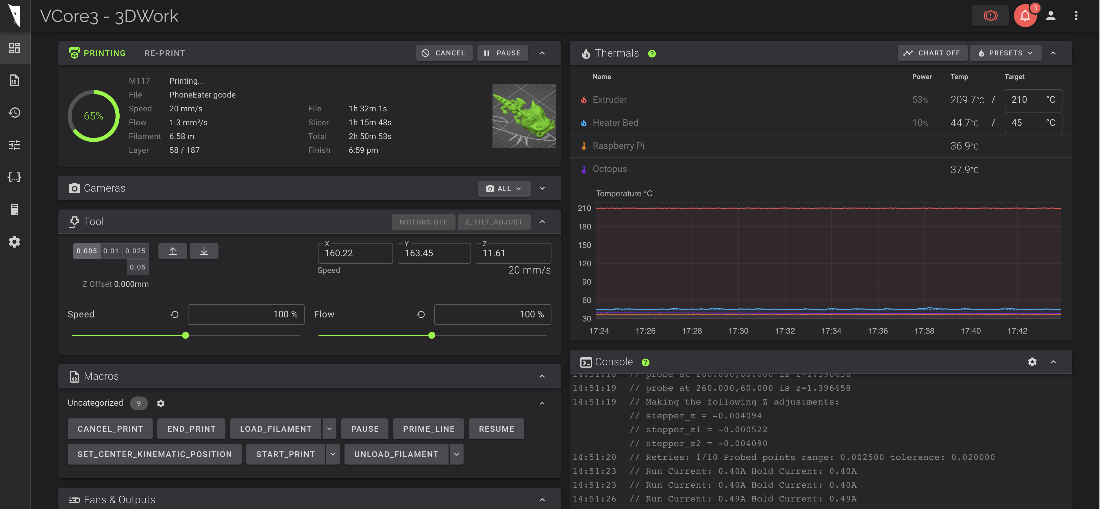
- We will check that we can access the VCoreOS interface using http://v-coreos.local/ or http://IP
Preparing our SKR Octopus
As we have already commented Klipper runs on our Raspberry Pi using our printer electronics as a basic motor and sensor controller.
So that Klipper can manage our electronics we must prepare it with a special firmware that we discussed in the previous point (VCoreOS) and for our SKR Octopus another pre-compiled firmware that we can download from this link.
We just have to put the name “firmware.bin” in our SD Card (note that we will have to rename it since the name with which we download it is “firmware-octopus-11.bin”)
We advise you to make the first update of your electronics, if it is supported directly, with the pre-compiled ones that we can download from here.
In case of not connecting because the Klipper and Klipper firmware versions do not match, perform the firmware update process using the USB cable following these instructions. And in the same way use it for future updates:
– Connect via SSH to our Raspberry Pi
– Make sure that the BTT Octopus does not have an SD Card inserted
– We launch the following command:
~/klipper_config/config/boards/btt-octopus-11/make-and-flash-mcu.sh which will compile the firmware and update directly the Octopus mountain bike
Configuring VCoreOS for our printer
Now that we have access to the web interface and VCoreOS and electronics communicate perfectly, we have to customize our configuration to adapt it to our needs.
For our configuration we make the following modifications in our printer
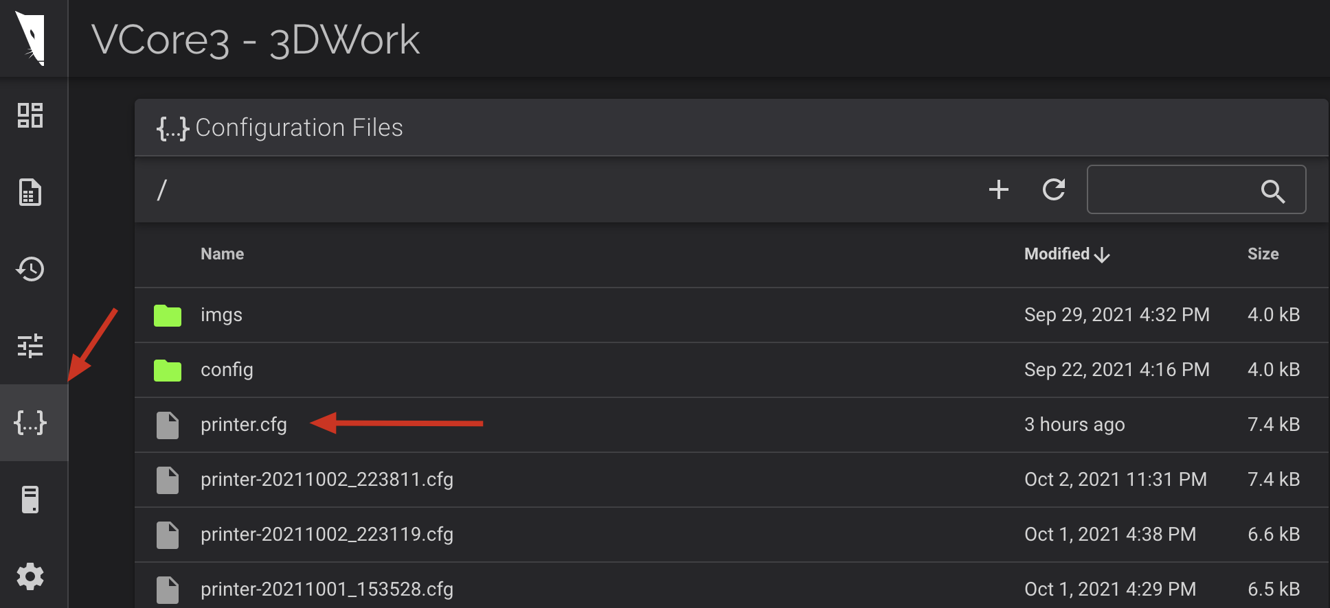
- We will indicate the electronics that we are going to use by removing the comment (#) in front of the line where the include is located:
### CONTROL BOARD
# [include config/boards/btt-skr-pro-12/config.cfg]
[include config/boards/btt-octopus-11/config.cfg]
- We continue with the basic configuration of our machine:
### BASE SETUP
[include config/printers/v-core-3/v-core-3.cfg]
[include config/printers/v-core-3/steppers.cfg]
[include config/printers/v-core-3/tmc2209.cfg]
- In our case we have used an accelerometer to adjust the acceleration.
# Uncomment this next line if you have an ADXL345 connected to the SKR PRO
[include config/sensors/adxl345.cfg]
- We also enable the PROBE since we have mounted a PINDAv2 sensor:
# Inductive/Capacitive probe
[include config/z-probe/probe.cfg]
[probe]
#z_offset: -1.430 # Adjust this to fit your setup
pin: ^probe_pin # Change this to suit your probe (NPN/PNP NO/NC) if necessary.
- Also, as we mentioned, we are going to use sensorless instead of physical limit switches and we will leave the latter commented:
# Physical endstops
#[include config/printers/v-core-3/physical-endstops.cfg]
#[safe_z_home]
#home_xy_position: 150,150 # 300mm printer
#home_xy_position: 200,200 # 400mm printer
#home_xy_position: 250,250 # 500mm printer

# Sensorless homing (Beware: this requires manual tinkering and does not work if your x/y stepper drivers
# have clipped DIAG pins). It is strongly encouraged to use physical endstops if you're a beginner.
# If you still wish to proceed, copy config/templates/sensorless-homing.cfg to the root directory and
# remove the # from the line below.
[include sensorless-homing.cfg]
- We will define the size of our printing area:
### PHYSICAL DIMENSIONS
# Remove the # from your printer size below.
# Similarly add a # in front of [include config/printers/v-core-3/300.cfg] if you have a bigger machine.
[include config/printers/v-core-3/300.cfg]
#[include config/printers/v-core-3/400.cfg]
#[include config/printers/v-core-3/500.cfg]
- We will adjust the scheme of accelerations and speeds:
### SPEED & ACCEL
# Acceleration
# Check https://www.klipper3d.org/Resonance_Compensation.html for input shaper calibration.
[include config/printers/v-core-3/speed-limits-basic.cfg]
# Do not enable this next line without actively cooled stepper drivers.
#[include config/printers/v-core-3/speed-limits-performance.cfg]
- We select our extrusion and hotend system, in our case Orbiter/Dragon:
### EXTRUSION

# Extruder
# [include config/extruders/bmg.cfg]
# [include config/extruders/lgx.cfg]
[include config/extruders/orbiter.cfg]
# [include config/extruders/hemera.cfg]
# [include config/extruders/titan.cfg]

# Hotend
# [include config/hotends/v6.cfg]
# [include config/hotends/copperhead.cfg]
# [include config/hotends/mosquito.cfg]
# [include config/hotends/mosquito-magnum.cfg]
[include config/hotends/dragon-standard-flow.cfg]
# [include config/hotends/dragon-high-flow.cfg]
- Since we are going to use a SKR TFT24 screen we will add it in the OVERRIDES section as well as the Input Shapper values:
### USER OVERRIDES
# Place all your overrides here

## 3DWORK TFT24 DISPLAY
[display]
lcd_type: emulated_st7920
spi_software_miso_pin: PA6
spi_software_mosi_pin: EXP1_3
spi_software_sclk_pin: EXP1_5
en_pin: EXP1_4
encoder_pins: ^EXP2_5, ^EXP2_3
click_pin: ^!EXP1_2

[output_pin beeper]
pin: EXP1_1

## 3DWORK RESONANCES
[input_shaper]
shaper_freq_x: 82.8
shaper_type_x: zv
shaper_freq_y: 63.6
shaper_type_y: mzv

[printer]
max_accel: 11000  # should not exceed the estimated max_accel for X and Y axes
We already have the basic settings to begin to verify that everything works correctly !!!
Pre-checks
Before starting to print anything, it is advisable to follow the following steps to verify correct operation.
- Belt tensioning
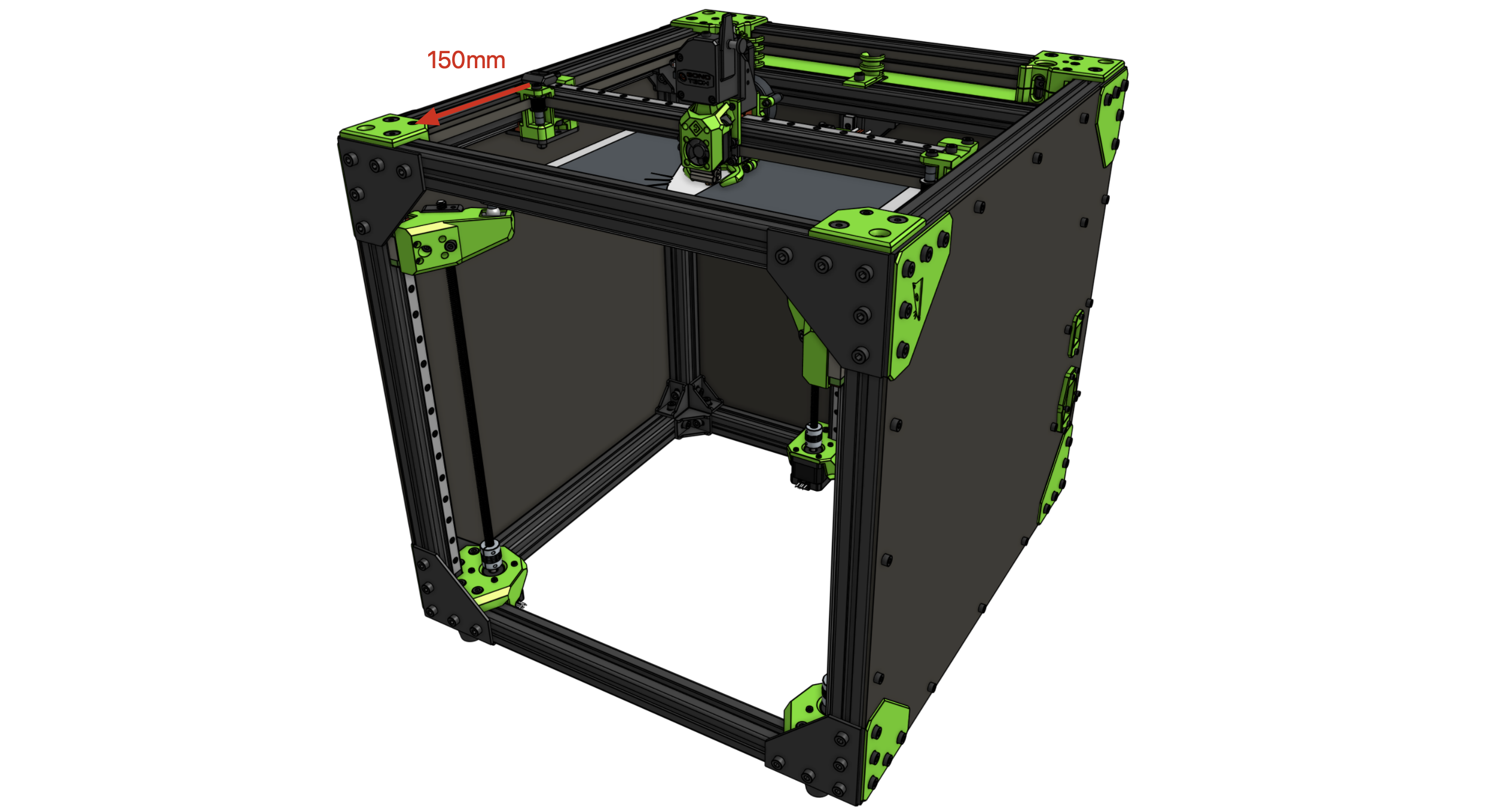
We are going to explain the process we follow to adjust the belt tension since in printers with kinematics CoreXY is vital that both belts that move the X and Y axis have the similar tension .- We will move our print head to the center of the bed and measure (see the screenshot below) 150mm between the axes of the front straps and the X axis.
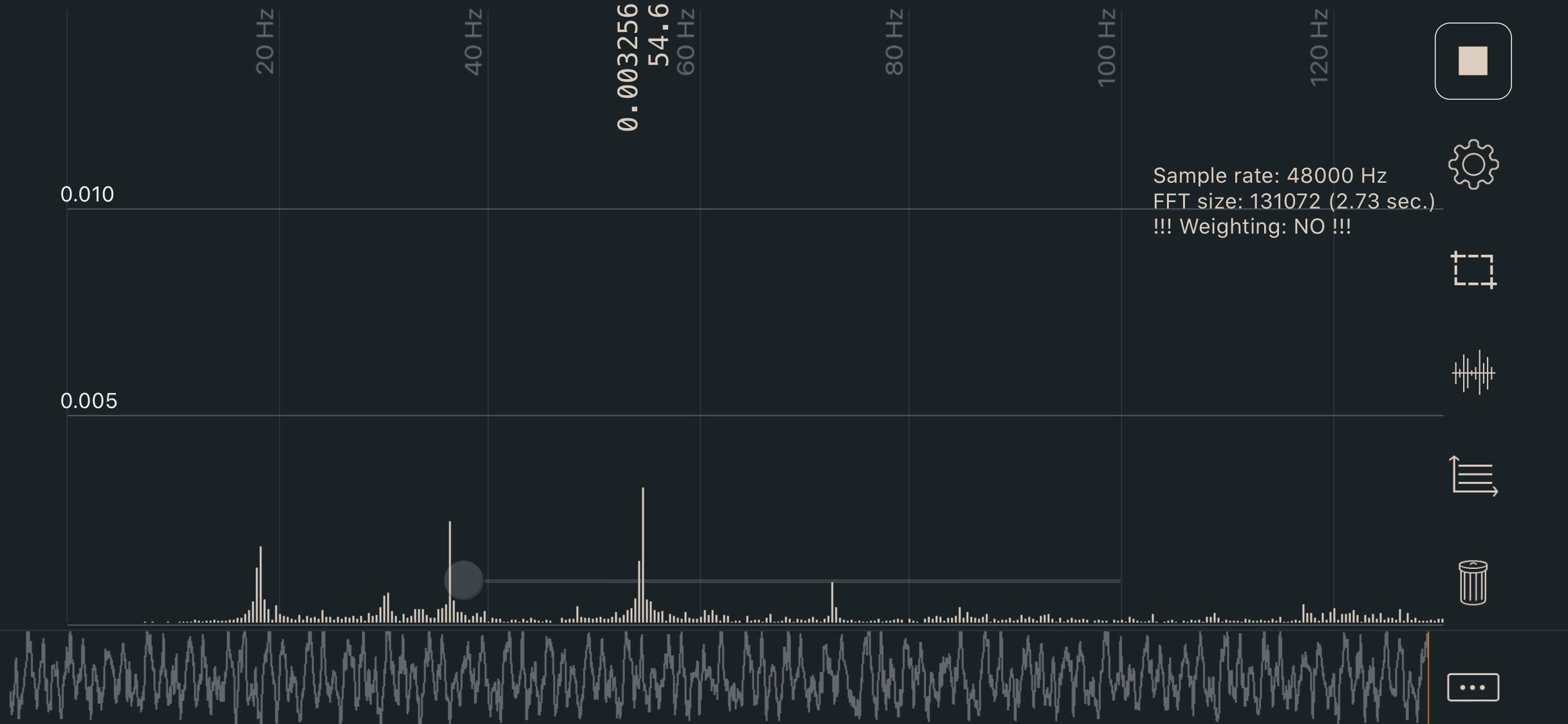
- Using an application called Sound Spectrum Analysis ( iOS ) or Spectroid ( Android ) we will use to measure the sound frequency generated when touching the strap, which has to be around 110Hz (the approximate equivalent of 2lb)
- Motor directions
To check that the motors are in the correct direction and with the printer turned off, we will manually place the print head in the center of the bed and then we will send the command / macro SET_CENTER_KINEMATIC_POSITION from the console.
Then we can use the Fluidd movement controls to verify that each axis moves in the correct direction.
In the event that the address is not correct, we must indicate it with a! (or remove it) in the definition of “dir_pin” of the engine.
[stepper_y]
dir_pin:! y_dir_pin # Add! in front of pin name to reverse AND stepper direction
- End stops / endstops
Once we have verified that the direction of our motors is correct we will have to check the following:- End of physical races : If they are used, we can check their status from the Fluidd interface itself , in the Tunning tab. The correct state is OPEN without being activated and TRIGGERED activated.
- Sensorless : If you choose to use sensorless you must adjust the sensitivity within the file printer.cfg adding an override of the default configuration:
[tmc2209 stepper_x]
driver_SGTHRS: 70 # Stall guard threshold, this is your X sensitivity, to adjust, copy this section and override it in printer.cfg.
[tmc2209 stepper_y]
driver_SGTHRS: 70 # Stall guard threshold, this is your Y sensitivity, to adjust, copy this section and override it in printer.cfg. - Z-Probe : If you have a leveling sensor, depending on the type we use, its verification may vary. In the case of inductive / capacitive / IR that usually function as physical limit switches, they are checked in the same way.
On the other hand sensors type BLTouch / 3DTouch or similar, which use a servo part, must be verified different using the BLTOUCH_DEBUG COMMAND = pin_down commands to display the pin, BLTOUCH_DEBUG COMMAND = touch_mode and verifying with QUERY_PROBE having to return a probe: open .
We will use the command BLTOUCH_DEBUG COMMAND=pin_up to raise the pin again. In the event that something does not work correctly and the sensor hangs (flashing red), we will return it to normal using BLTOUCH_DEBUG COMMAND=reset.
- Z-Offset, in the case of using a leveling sensor we must adjust the Z-Offset, which is the distance between which the sensor is activated when detecting the bed and the nozzle. For this we will use the PROBE_CALIBRATE command to enter the calibration.
Once the positioning process is finished, we will use the traditional folio and the TESTZ Z=-.1 commands (we can vary the value to our liking) to adjust Z until the folio rubs against the nozzle.
When we have the appropriate value we will use the ACCEPT command which will save the obtained value in our printer.cfg, this is the lower area of values that are auto-generated and should not be modified:
#*# [probe]
#*# z_offset = 1.4
In the case of wanting to adjust it manually, we can modify that value.
Start-up and initial setup
We now have the machine ready to continue with the important initial adjustments to be made before starting the initial calibration.
PID setting
The PID adjustment is an important point to carry out during commissioning and whenever we modify any part / component related to the heating system.
The process is very simple and done very quickly, so we have no excuse to avoid doing it whenever we see abnormal fluctuations in temperature:
- Hotend / Extruder , we will launch the command PIDCALIBRATE from the terminal, for example:
PID_CALIBRATE HEATER = extruder TARGET = 200 - Bed , in this case we will launch the command as follows:
PID_CALIBRATE HEATER = heater_bed TARGET = 60
Once both commands are finished, we will SAVE_CONFIG so that they are saved in our “printer.cfg”
Bed leveling
VCoreOS already has the configuration startup macros to perform bed leveling. In any case we provide the link to the Klipper documentation on leveling to customize or explore other options if we deem it appropriate.
Compensation of resonances (Input Shaping)
One of the great features of Klipper, and that we will see soon in other firmwares such as Marlin or Duet, is the support for Input Shaping .
This is a technique that reduces vibrations / waves (ringing, echoin, ghosting, rippling are other names for this type of artifact).
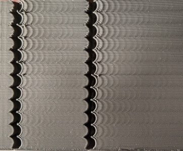
This type of artifact is produced by mechanical vibrations normally caused by sudden movements when changing directions.
These can be a not sufficiently rigid chassis, little or little tension belts, alignment problems in chassis parts or kinematics, large mass movements in the movement axes, etc.
Due to this, it is advisable that before beginning these adjustments we make sure that we have tried to solve as much as possible the most common faults mentioned.
Ratrig has done a exceptional job with the chassis and kinematics design of this VCore3, so most failure points are minimized to a minimum.
Since it is a very extensive process, we are going to explain the two ways to adjust Input Shaping, providing links to the official documentation.
Remind you that we will use a caliper or caliper to measure the resonances of our machine:
- Manual resonance compensation: in this case and through a test tower we can find and adjust the Input Shaping values by following the instructions in the previous link.
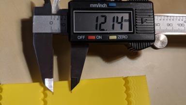
- Resonance compensation using an accelerometer: In our case, when using it on other machines, we opted to use an ADXL345 accelerometer for automatic resonance measurement.
The process is a bit laborious in the installation of certain software components and requires extra cabling, but for the results obtained we believe that it is worth it. And since VCoreOS supports it by default, we connect the accelerometer directly to our Octopus BTT.
Pressure Advance
Pressure Advance is another interesting Klipper feature that also has similar features in other firmwares.
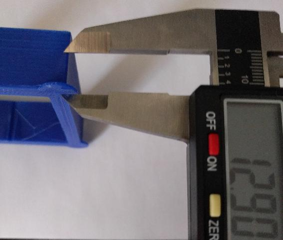
Pressure Advance allows us total control over extrusion avoiding artifacts such as threads or filament remains in movements without extrusion or improving the finish in changes of direction in our pieces.
To measure our Pressure Advance value we will use a tower of test designed to highlight these flaws and follow the procedure described in the following link.
Slicer Configuration (filleting)
VCoreOS comes with some predefined macros that we can call directly from our Slicer. This allows us centrally from Klipper to manage the start, end or other gcodes that may interest us.
We can find the START_PRINT and END_PRINT macro in config / printers / vcore3 / macros.cfg . In any case depending on our slicer we will have to make some adjustments:
Start GCode
M190 S0 ; Prevents prusaslicer from prepending m190 to the gcode ruining our macro
M109 S0 ; Prevents prusaslicer from prepending m109 to the gcode ruining our macro
START_PRINT EXTRUDER_TEMP=[first_layer_temperature] BED_TEMP=[first_layer_bed_temperature]
End GCode
END_PRINT
Start GCode
START_PRINT EXTRUDER_TEMP=[first_layer_temperature] BED_TEMP=[first_layer_bed_temperature]
End GCode
END_PRINT
Start GCode
START_PRINT EXTRUDER_TEMP={material_print_temperature} BED_TEMP={material_bed_temperature}
End GCode
END_PRINT
Start GCode
START_PRINT EXTRUDER_TEMP={temperature_extruder1} BED_TEMP={temperature_heatbed}
End GCode
END_PRINT
Start GCode
START_PRINT EXTRUDER_TEMP=[extruder0_temperature] BED_TEMP=[bed0_temperature]
End GCode
END_PRINT
User experience
The VCore3 from Ratrig is a impressive printer, always understanding that we are talking about a machine for medium / advanced users with some experience. Or simply wanting to learn to handle 3D printers that go beyond the usual standard of Cartesian printers and that usually use Marlin.
Thanks to the documentation, design of printed parts and qualities in the components the assembly and handling of the printer is relatively simple considering that it is an advanced printer.
Being able to manage the machine from any device thanks to Fluidd, our LCD screen or even using a screen on our Raspberry Pi is certainly a real delight.
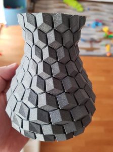
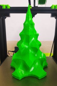
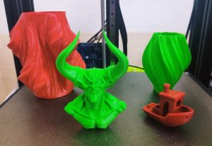
Once assembled, made the basic machine / firmware adjustments and calibrations of our slicer, we can say that the quality and reliability of the printer has been superb in all the tests and trials carried out.
Here are some examples:
Maintenance
We recommend a series of points to check regularly to keep our printer in optimal condition:
- Check the tension of the belt, which may lose tension with use. If this is your case and it loses tension in a constant way, check the components of the kinematics in search of hardware failures.
- Cleaning the extruder / hotend of filament remains or using cleaning filament to maintain our barrel and nozzle in perfect condition.
- Check, clean and lubricate our linear guides, bearings, gears and pulleys of our kinematics with special lithium grease.
- Clean and lubricate the ventilation system extrusion, electronics and power supply.
- Clean our PEI sheet or printing surface regularly with IPA (Isopropyl Alcohol)
- Replace the “consumables” of our printer when necessary. Nozzles, Barrel, PEI, PTFE (50-100 hours approximately)
Backup VCoreOS / Klipper
Something very advisable is to have a backup of the firmware of our printer, we are going to show you how we do it to have a backup that can save us in case of a disaster with our SD.
Creating our repository on Github

In our case we will use Github as an option to have a backup of our printers. So first, and if we don’t already have it, we’ll open a free account at Github and we will create a repository for our printer.
In our case we will call it vcore3_3dwork , which we will use to save the configuration of our klipper_config directory
Configuring the backup
Accessing our Raspberry Pi by SSH, using Terminus for example as an SSH client, we will make sure that we have the git client installed :
sudo apt-get install git -y
We will go to our klipper_config folder and mount our git
cd ~/klipper_config/
git init
git remote add origin <URL-Repositorio-GitHub>
git add .
git commit -m "Backup inicial :D"
git push -u origin master
If everything went well, it will ask you for the email and password of your Github account and as soon as it is synchronized you will be able to enter your account and see all your files. Remember to do this process periodically when making important changes above all!
Restoring a backup
Let’s hope you don’t need it first! But in case you need to restore your files we have the following options available:
Restoring manually
We can go to our repository on Github and copy each file line by line or download our repository in zip and copy them to our SD from the computer or transferring by SSH using a WinSCP style tool or similar.
Restoring from Git
In the case of wanting to completely restore our configuration for the one we have in Github and we have the original klipper_config directory, we will carry out the following process:
cd ~/klipper_config/
git fetch -all
git reset --hard origin/master
If we want to reinstall from a new installation we will carry out the following steps
cd ~
git clone <URL-Repositorio-GitHub>
Final assessment
The VCore3 has seemed to us an exceptional machine in practically all its aspects, making it undoubtedly one of the best “premium” kit printers available on the market.
The price of the basic kits, such as the 300×300 VCore3 for around 499€ taking into account the quality of the components is a more than adequate price for this type of machine.
And if we also complete the kit with electronics, motors and other sensors, we will have a “premium” machine at around 1000€, a fairly contained price actually.
We also have kits adaptable to our needs, with very detailed and complete assembly guides, greatly facilitating the assembly process.
And all this with great support from Ratrig with his VCoreOS and his documentation supporting the most common electronics for this type of machine. In short, a printer to take into account if we need something “serious” for our 3D projects.
As always from 3DWork we hope you liked this article. You can find other articles of interest here:
- BTT Octopus Pro: Natural evolution of Octopus for high performance and speed machines
- The best resin 3D printers in 2021
- Longer LK5 Pro: Review of a High-Volume Desktop 3D Printer
- Nozzle: Learn all the basics about this essential component
- Elegoo Mars 2 Pro: Review of a great resin printer for home use
- BTT Octopus: Analysis and Setup Guide with Marlin and Klipper
- FYSETC S6: Complete guide to this excellent electronic board for our 3D printers
- BTT SKR 2: How to detect and repair the failure of the first revisions (REV A)
- Elegoo Jupiter 6K: A new flagship arrives on the Crowdfunding platform Kickstarter
- Monoprice Mini Delta v2: The perfect choice to get started in 3D printing
- 3D printed Simpsons TV that plays the episodes randomly
- BigTreeTech SKR 2: Guide and setup of this new electronics
- Complete guide Fysetc Spider: A real “beast” for our 3D printers
- New Marlin Builder v2.0 update (+220 firmwares available v2.0.9.1)
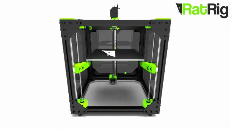













Almost perfect. It’s based on linear RAILS, not the traditional linear guides on prusa-style. Totally different.