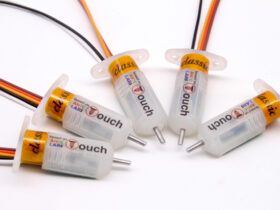
Recently a colleague sent me a BLTouch / 3DTouch sensor from the Geeetech brand. I usually use optical infrared sensors for my printers, but I wanted to try the BLTouch sensors since none had fallen yet by my hands. So I got down to work for Configure BLTouch with BabyStepping in the last Marlin available today and satiate my curiosity.
I have always used leveling sensors on my machines, as leveling the four corners of the printing surface with a folio is definitely not my thing. Nor do I see it practical and much less precise, although at this point I surely disagree with some reader 🙂
I have to say that I tried quite a few inductive and capacitive sensors, I even opted for the original PINDA 2 , which is very comfortable to install since is one of the few that actually powers 5V and gives quite a bit of precision. But it didn’t convince me either. In each and every one of them a common denominator, the detection distance varies depending on the metal and even the temperature of the bed.
It’s something I don’t like at all. It doesn’t give me any sense of precision, since what I’m looking for is an immutable (or at least minimal) measurement. Having a component that according to the conditions of use works differently has no meaning whatsoever. I don’t want to calibrate that distance again if I change the filament from PLA to ABS, it’s a hassle.
With the optical sensors, which I love, we forget about these variations since under normal conditions they do not affect the type of metal or the temperature. And with the BLTouch the same, since they are completely mechanical sensors (hence my desire to try it).
Introduction
Before starting I have to confess that I do not have a commercial 3D printer as many of you may have ( Anet A8 , Ender3 or Artillery X1 for example). I had a commercial at the beginning (a completely disaster), so I decided to design and manufacture my own to my liking and needs.
However, you should not worry because when configuring the BLTouch sensor the options to be modified in the Marlin firmware will be exactly the same . The only thing that will vary will be the connections, but we will indicate some examples so that you do not have any problem in its corresponding section.
In this article we will only discuss the options to modify to support BLTouch / 3DTouch. If you need to completely configure Marlin do not hesitate to visit the Complete guide: Configure Marlin 2.0.3 from scratch and not die trying that you also have available on our website.
Why use BLTouch / 3DTouch?
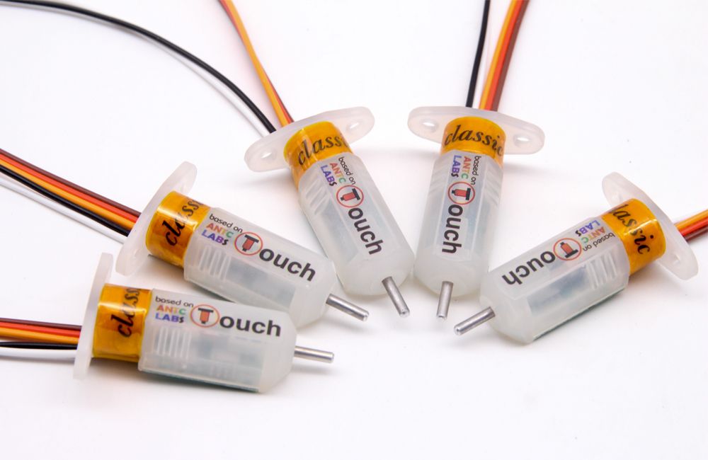
The main reason for me would be not having to be leveling 4 corners with a sheet of paper or making squares in bed. If we make the leveling of the printing surface in the 4 corners, when you are leveling one another it is unbalanced. In the end, so that everything is square, you end up making several passes, especially if you are a precision maniac.
So the question is extremely simple. Why not install a leveling sensor to level at a single central point in the bed (SAFE_HOMING), and let Marlin generate the mesh of points and worry about the rest? That’s what Marlin is for, to make life easier for us.
For more reasons, you can install capacitive or inductive sensors, but these types of sensors vary depending on the temperature of the bed and the metal. The higher the temperature, the lower the detection range. So you can not leave a fixed value for PLA and another for ABS.
In addition, on aluminum the detection range of capacitive and conductive sensors is considerably reduced with respect to using steel or iron. Another negative point since if you use glass you will be very fair and in any failure your nozzle will go through the glass with the consequent risk of breakage.
BLTouch / 3DTouch sensors are mechanical, so they are not affected by heat, humidity or the type of material on your printing surface.
Furthermore, the connection of the BLTouch / 3DTouch sensors to the boards is relatively simple and you do not need to carry out any electronic modification as it happens in other sensors. Some Chinese sensors indicate operating ranges from 6-36v, nothing is further from reality. If you feed them at minimum values they don’t work, so you have to feed them at 12v.
The problem comes when you have to send the signal (S) to your electronic board, if you don’t regulate that voltage (with additional electronics) you can burn the port as it happened to me in my MKS Gen v1.4. The result was that the Z- was completely unusable for me having inserted 12v. in a 5v input. It is not a major problem, you can change within the Marlin firmware and indicate that for Z- we are going to use the Z+, but you have to make unnecessary modifications.
Where can I buy a BLTouch / 3DTouch?
You can buy this type of sensor in any online store, since they are very common in the world of 3D printing. Below I leave you two affiliate links to Amazon and Banggood. Of course you can buy them wherever you want, there are dozens of pages.
If you decide to acquire it through these links, it is my duty to tell you that a small commission will go to the 3DWork.io project and we will be eternally grateful to you. In this way we can continue writing 3D printing guides and articles on interest. Or alternatively, you can follow us on our social networks.
| BLTouch Original (Antclabs) | |||
| 3DTouch | |||
| Bigtreetech 3DTouch v3.0 | |||
| Creality 3D BLTouch v2 |
Or if you wish, you can use our component search engine Markets.sx, where you can compare prices in different Marketplaces (Amazon, Aliexpress, Banggood, etc.) with a single search and very easily.
Configure BLTouch / 3DTouch in Marlin
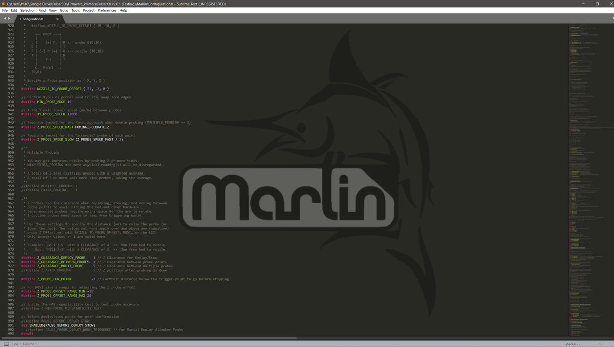
Well, let’s start configuring our Marlin firmware to support BLTouch / 3DTouch sensors. As I explained in the previous article of Configure Marlin 2.0.3 from scratch, to activate the options you simply have to uncomment them. This is done by removing the two bars in front of each #define, this way the compiler can make use of them and add them to the final firmware.
We will start the configuration by editing the file Configuration.h with your favorite text editor (mine is Sublime). Once you have edited it, we are going to indicate to our dear Marlin that our 3D printer has a limit switch (sensor) on the Z axis. We will proceed to uncomment the USE_ZMIN_PLUG options.
// Specify here all the endstop connectors that are connected to any endstop or probe.
// Almost all printers will be using one per axis. Probes will use one or more of the
// extra connectors. Leave undefined any used for non-endstop and non-probe purposes.
#define USE_XMIN_PLUG
#define USE_YMIN_PLUG
#define USE_ZMIN_PLUG
//#define USE_XMAX_PLUG
//#define USE_YMAX_PLUG
//#define USE_ZMAX_PLUG
Now we uncomment the option Z_MIN_PROBE_USES_Z_MIN_ENDSTOP_PIN.
/**
 * Z_MIN_PROBE_USES_Z_MIN_ENDSTOP_PIN
 *
 * Enable this option for a probe connected to the Z Min endstop pin.
 */
#define Z_MIN_PROBE_USES_Z_MIN_ENDSTOP_PIN
And in this other line of the code we are going to indicate that our installed sensor is a BLTouch / 3DTouch, which for Marlin come to be the same.
/**
 * The BLTouch probe uses a Hall effect sensor and emulates a servo.
 */
#define BLTOUCH
If we use a self-leveling sensor (either BLTouch or any other), we must indicate to Marlin the position of the sensor with respect to our print nozzle. This will necessarily be separated and we will define it as coordinates and in millimeters.
My leveling BLTouch is 37mm to the right of the nozzle, and 2mm behind it, so I would put the following settings. You must measure these values to enter on your printer (do not use mine).
/**
 * Z Probe to nozzle (X,Y) offset, relative to (0, 0).
 *
 * In the following example the X and Y offsets are both positive:
 *
 *   #define NOZZLE_TO_PROBE_OFFSET { 10, 10, 0 }
 *
 *     +-- BACK ---+
 *     |           |
 *   L |    (+) P  | R <-- probe (20,20)
 *   E |           | I
 *   F | (-) N (+) | G <-- nozzle (10,10)
 *   T |           | H
 *     |    (-)    | T
 *     |           |
 *     O-- FRONT --+
 *   (0,0)
 *
 * Specify a Probe position as { X, Y, Z }
 */
#define NOZZLE_TO_PROBE_OFFSET { 37, -2, 0 }
Now we must uncomment the AUTO_BED_LEVELING_BILINEAR function and then the RESTORE_LEVELING_AFTER_G28 function, so that they remain active in our firmware.
/**
 * Choose one of the options below to enable G29 Bed Leveling. The parameters
 * and behavior of G29 will change depending on your selection.
 *
 *  If using a Probe for Z Homing, enable Z_SAFE_HOMING also!
 *
 * - AUTO_BED_LEVELING_3POINT
 *   Probe 3 arbitrary points on the bed (that aren't collinear)
 *   You specify the XY coordinates of all 3 points.
 *   The result is a single tilted plane. Best for a flat bed.
 *
 * - AUTO_BED_LEVELING_LINEAR
 *   Probe several points in a grid.
 *   You specify the rectangle and the density of sample points.
 *   The result is a single tilted plane. Best for a flat bed.
 *
 * - AUTO_BED_LEVELING_BILINEAR
 *   Probe several points in a grid.
 *   You specify the rectangle and the density of sample points.
 *   The result is a mesh, best for large or uneven beds.
 *
 * - AUTO_BED_LEVELING_UBL (Unified Bed Leveling)
 *   A comprehensive bed leveling system combining the features and benefits
 *   of other systems. UBL also includes integrated Mesh Generation, Mesh
 *   Validation and Mesh Editing systems.
 *
 * - MESH_BED_LEVELING
 *   Probe a grid manually
 *   The result is a mesh, suitable for large or uneven beds. (See BILINEAR.)
 *   For machines without a probe, Mesh Bed Leveling provides a method to perform
 *   leveling in steps so you can manually adjust the Z height at each grid-point.
 *   With an LCD controller the process is guided step-by-step.
 */
//#define AUTO_BED_LEVELING_3POINT
//#define AUTO_BED_LEVELING_LINEAR
#define AUTO_BED_LEVELING_BILINEAR
//#define AUTO_BED_LEVELING_UBL
//#define MESH_BED_LEVELING

/**
 * Normally G28 leaves leveling disabled on completion. Enable
 * this option to have G28 restore the prior leveling state.
 */
#define RESTORE_LEVELING_AFTER_G28
Once the type of self-leveling that we want Marlin to carry out is configured, we will indicate with the GRID_MAX_POINTS parameters the number of probes (or tests) to be carried out. I usually make 9 checkpoints before each print, you can expand or reduce it, that is up to you.
// Set the number of grid points per dimension.
#define GRID_MAX_POINTS_X 3
#define GRID_MAX_POINTS_Y GRID_MAX_POINTS_X
And since I always like to do HOMING in the center of the bed for safety, I activate the Z_SAFE_HOMING option.
#define Z_SAFE_HOMING

#if ENABLED(Z_SAFE_HOMING)
#define Z_SAFE_HOMING_X_POINT ((X_BED_SIZE) / 2) // X point for Z homing when homing all axes (G28).
#define Z_SAFE_HOMING_Y_POINT ((Y_BED_SIZE) / 2) // Y point for Z homing when homing all axes (G28).
#endif
Now we will save the Configuration.h file and edit a new file called Configuration_adv.h . The difference compared to Configuration.h is that it offers us more detailed customization options, and experimental or in development functions.
In my printer I use a leveling function available in Marlin 2 called BABYSTEPPING. This function allows me to calibrate the height of my leveling sensor in the center of the bed once with a sheet of paper.
Later, the printer will perform 9 probe points automatically at the beginning of each print. This way I won’t have to go corner by corner unnecessarily to calibrate my bed. By default it is deactivated, so we will activate the BABYSTEPPING option, as I show you below:
#define BABYSTEPPING
#if ENABLED(BABYSTEPPING)
//#define BABYSTEP_WITHOUT_HOMING
//#define BABYSTEP_XY // Also enable X/Y Babystepping. Not supported on DELTA!
#define BABYSTEP_INVERT_Z false // Change if Z babysteps should go the other way
#define BABYSTEP_MULTIPLICATOR_Z 20 // Babysteps are very small. Increase for faster motion.
#define BABYSTEP_MULTIPLICATOR_XY 1

#define DOUBLECLICK_FOR_Z_BABYSTEPPING // Double-click on the Status Screen for Z Babystepping.
#if ENABLED(DOUBLECLICK_FOR_Z_BABYSTEPPING)
#define DOUBLECLICK_MAX_INTERVAL 1250 // Maximum interval between clicks, in milliseconds.
// Note: Extra time may be added to mitigate controller latency.
#define BABYSTEP_ALWAYS_AVAILABLE // Allow babystepping at all times (not just during movement).
//#define MOVE_Z_WHEN_IDLE // Jump to the move Z menu on doubleclick when printer is idle.
#if ENABLED(MOVE_Z_WHEN_IDLE)
#define MOVE_Z_IDLE_MULTIPLICATOR 1 // Multiply 1mm by this factor for the move step size.
#endif
#endif

//#define BABYSTEP_DISPLAY_TOTAL // Display total babysteps since last G28

#define BABYSTEP_ZPROBE_OFFSET // Combine M851 Z and Babystepping
#if ENABLED(BABYSTEP_ZPROBE_OFFSET)
//#define BABYSTEP_HOTEND_Z_OFFSET // For multiple hotends, babystep relative Z offsets
#define BABYSTEP_ZPROBE_GFX_OVERLAY // Enable graphical overlay on Z-offset editor
#endif
#endif
Well, these would be the basic options to configure your BLTouch. Of course, you can configure much more parameters such as limits, polls, travel speeds, etc. But for starters it is more than enough.
Installing BLTouch / 3DTouch
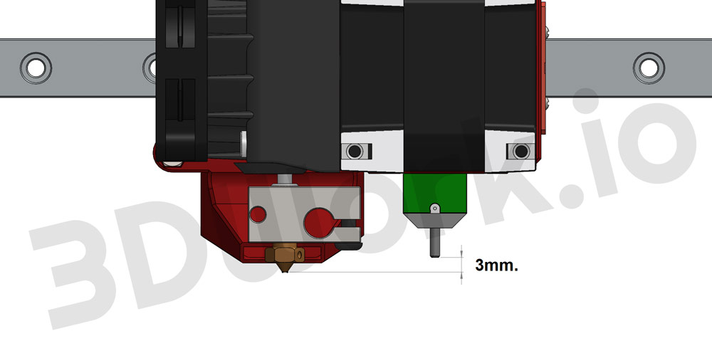
Regardless of where it is located with respect to the X and Y axes, which are the ones you must configure in Marlin, you have to position the BLTouch / 3DTouch sensor at a certain distance in height from your nozzle.
It is logically has to be within its range of action. When the probe is retracted, it must be above the nozzle (otherwise we will have problems). And when it is extended, it must lower several millimeters below the nozzle to be able to act.
The recommended is 2mm. As I have seen in some places, but it was a little short after some tests and I decided to set it to 2.5mm. that works for me correctly. Of course, this distance is at your absolute choice, it is only a guideline value.
BLTouch / 3DTouch electronic connection
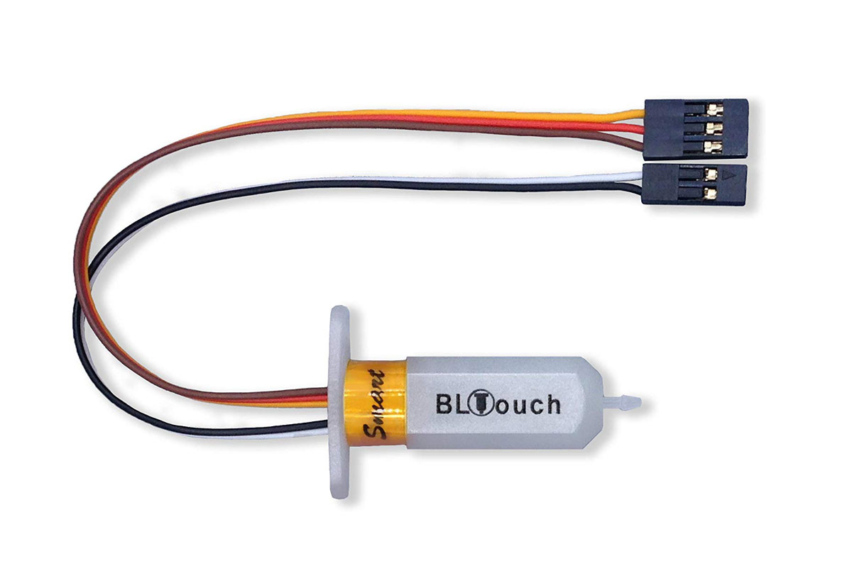
As you can see in this image, the BLTouch / 3DTouch leveling sensors have two connection cables. One with three pins and the other with two pins, which will be the ones we will need to connect to our electronics.
In my case, I use MKS Gen v1.4, so the connection couldn’t be easier (just like in RAMPS). Below I leave you 2 images so you can see where the BLTouch would be connected on my board, and on a RAMPS board, much more common than the one I own.
MKS Gen v1.4 board connection
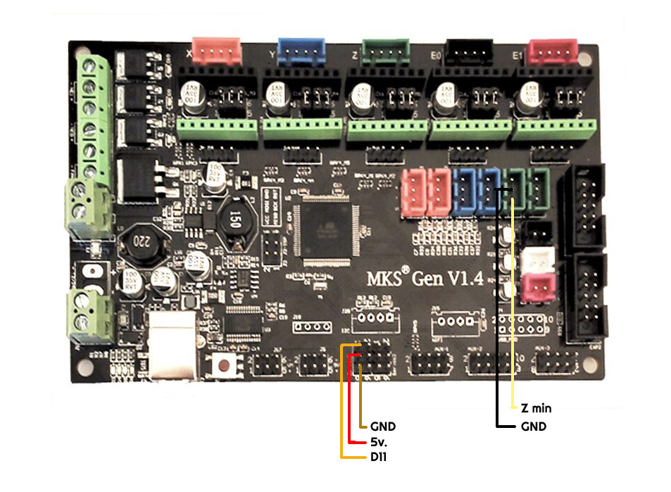
Very easy as you have been able to check, click on those 2 sites and that’s it. When you turn on the printer you will see that the sensor does a little checking (unfolds and retracts the probe).
RAMPS board connection
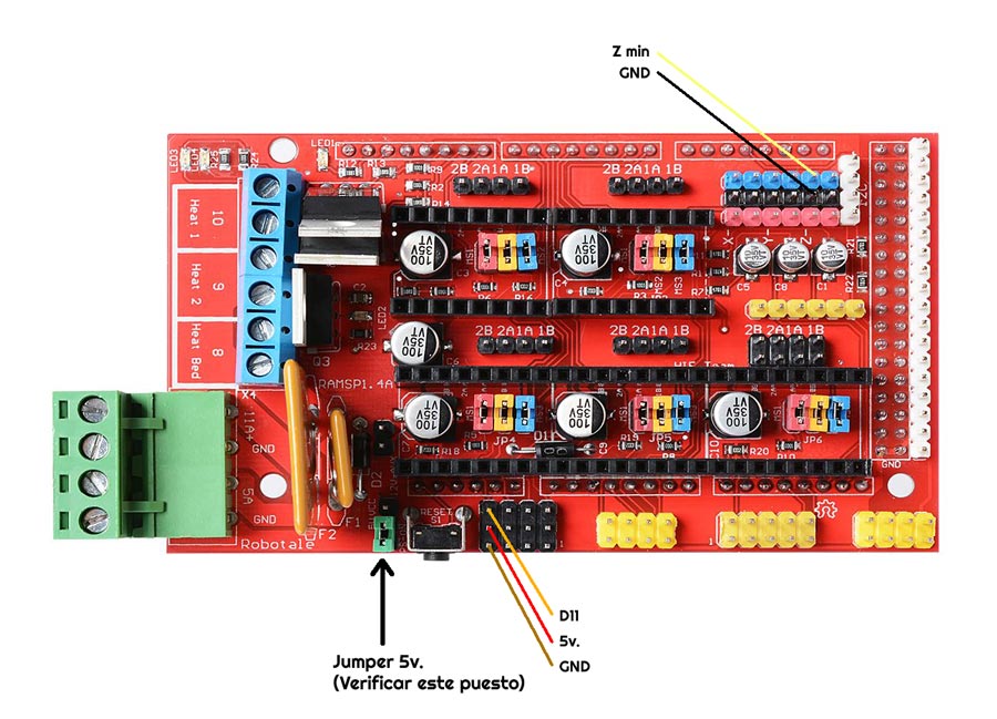
This connection is similar, but you must make sure that you have the jumper activated, so we will make sure that the level sensor reaches the 5v. necessary (very important).
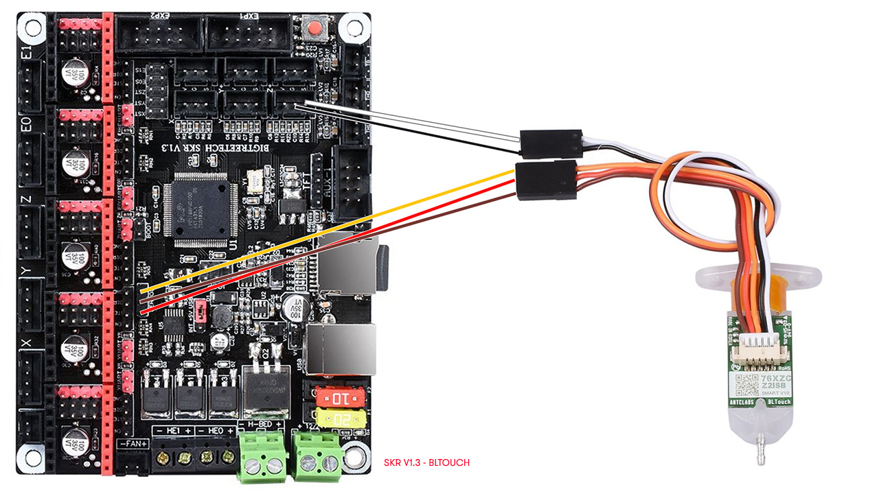
SKR v1.3 board connection
SKR v1.4 board connection
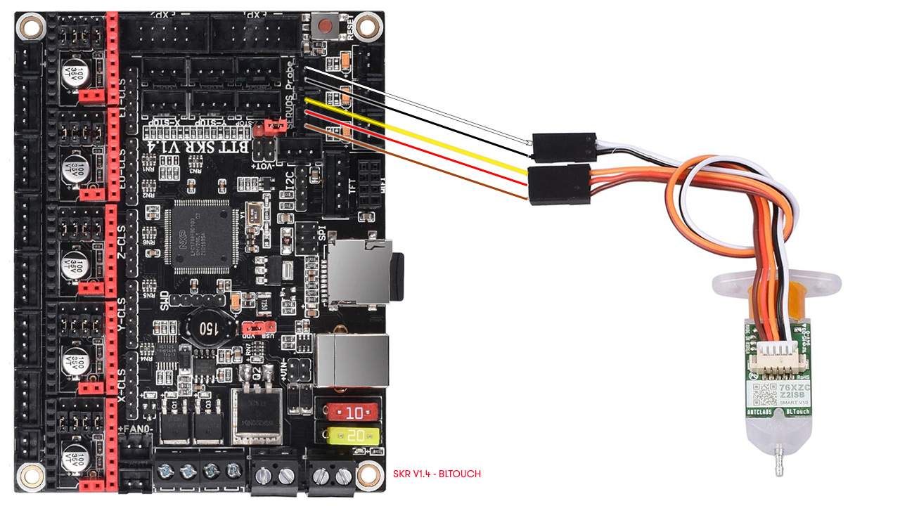
Just one important thing. In the case that connecting the 2 wires to the Probe connector the sensor not works, try to connect to the ZMin connector. Depending of the firmware version of your Marlin, in some cases it gives issues, but if you connect to ZMin it will work perfectly.
Initial script (GCODE commands)
You will need to add the self-leveling function at the beginning of each print. This is done very easily by configuring yourself in your favorite Slicer (Repetier, Simplify3D, Cura, etc.). It is simply adding the G29 command to level your head before each impression.
I leave you an example of my startup script on each print:
G28          ; Make HOME on all axes
G29          ; Auto-leveling command
G1 Z5 F5000  ; Nozzle up
M75          ; Launch timer
Configuring the offset
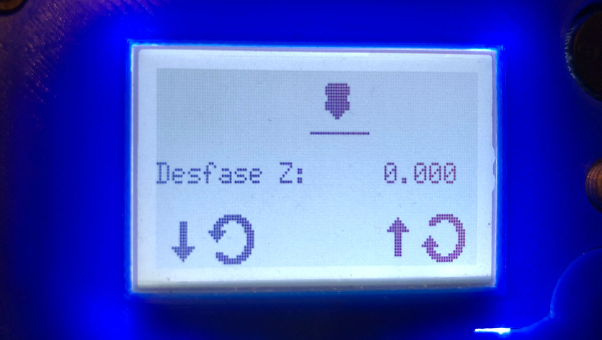
To finish, and having activated BabyStepping you will have your own menu called Offset. You can access it before the printing process and during (yes, you read me correctly) the printing process by pressing the button twice on your display.
In this way, and in real time, you can adjust the offset while you are making the first printing perimeters, and leave a perfect fit. To me this has saved me the odd impression, the truth is that it is quite useful.
Once you have made the offset settings, don’t forget to save the value in memory. You should have an option called Record to EEPROM , as long as you have supported it in your Marlin. If you can’t find it, you can alternatively run the command M500 (Save settings). This will store all the current settings in your EEPROM permanently.
If you have read the complete article, I congratulate you. It would not be surprising if he had left me something in the pipeline, if so, do not hesitate to notify me in the comments at the end of the article Install and configure BLTouch / 3DTouch in Marlin 2.0.x (MKS Gen, SKR, Anet A8, RAMPS).
Finally remind you, as always, that you can find us on our Telegram channel full of maniacs by 3D printing at next link, or on our social networks (don’t forget to follow us if you like the web).
If you wish, you can find other interesting articles in 3DWork at the following links:
- Complete guide SKR v1.4 / v1.4 Turbo with TMC2209 Sensorless drivers and Display TFT35 V3.0
- DyzeXtruder Pro: Analysis of a high-performance extruder for professional environments
- MKS TFT35 Display: Latest updates v106 and v107 available
- The Spaghetti Detective: Monitoring Octoprint from the Internet safely
- Powering the Raspberry Pi from the power supply of your 3D printer
- Booting our Raspberry Pi from USB with an SSD hard drive (or pendrive)
- Maker Ultimate 2: Review of the latest Monoprice printer
- Analyzing the new resin printer Phrozen Sonic Mini (Review)
- MKS Robin Nano v1.2: Analyzing the new MakerBase 32bit boards
- Hollow 3D objects with ChiTuBox to save resin
- 10 reasons to use ChiTuBox with your resin printer (SLA / DLP)

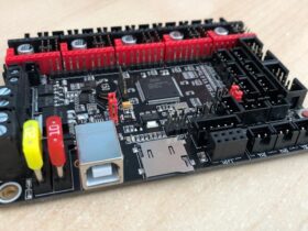
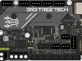
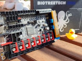













I have a MKS SGEN LPC1769 mainboard. Any idea where the 3 wire connector goes on this board? The 2 wire is the same as your example, but the spot that you show on the boards don’t exist on mine.
3 wire connector goes to servos. pin 23 is signal wire.
the best instructions on the internet
Thanks a lot for your comment!
Best regards
thank you for this little tutorial which is very useful
you forgot to mention the adjustment of the bed surface (the most important)
which to change file in version 2.0 of marlin
probe_selected in the configuration_adv.h file
for what its interresse here is a link with all the explanation for this setting
https://3dprinting.stackexchange.com/questions/8153/how-to-set-z-probe-boundary-limits-in-firmware-when-using-automatic-bed-leveling
Hello, thank you for your article. I just have a question, you mention you burnt your MKS board by sending a 12V signal to a 5V pin. Is the schematics that you provide in your article is the good one to avoid frying a board ? Thank you !
This happened me with different sensor (inductive), that needed 12v for operate properly. For bltouch you not must be worried of this, just connecting to the sockets that appear in the article will feed at his correct voltage without any issue.
Regards!
Hi I have a skr pro v1.2 and picked up a 3d touch the board hS a special place for the bl touch/3d touch… my 3d touch touch does not have aa connection for that spot ware would I plug it in on that board…
Hello,
Yes, you can connect to the SKR Pro due it have dedicated connector. Just check pinout and plug it properly.
If you have issues with some versions of Marlin (sometimes happen), use the ZMin connector.
Best regards!
What would i change if I wasnt using the mechanical z endstop? Instead using thr bltouch as the z endstop?
I’ve got mine working but for some reason the five buttons do not work
Hello I have followed all the steps above but I seem to be having a problem when I click auto home X and Y home as normal but as soon as Z trys to home the X and Z position is set to X70Y103 but they are still at X0Y0 position any ideas on what I’ve done wrong?
If you desire to do homing of Z in the center of the printing surface, you need to enable the option Z_SAFE_HOMING in your firmware Marlin. Search for it, and uncomment the line once you find it.
Regards!
I have it enabled the problem is homing to X0Y0Z10
When I home my printer it says on the LCD X70Y103Z10 but the position of the nozzle is at X0Y0Z10 it’s hard to explain I have a video but I can’t post it here
Here is a link to a Facebook page where I posted it to try figure it out
https://m.facebook.com/groups/669068986490743/permalink/3757612467636364/?ref=m_notif¬if_t=group_comment
I managed to figure it out it was because I had Z_MAX_ENDSTOP enabled
Thank you,
Only issue was a compile error telling me the MOVE_Z_WHEN_IDLE and BABYSTEP_ALWAYS_AVAILABLE were not compatable. I commented out move_z… and no more error.
Using Marlin Bug-Fix 2.0 with bug fixes, downloaded 2/19/2021
Hello,
Well, this option i never enable, and you will see that in the article appears as disabled (so perhaps you added by mistake). This is what appears:
//#define MOVE_Z_WHEN_IDLE // Jump to the move Z menu on doubleclick when printer is idle.
#if ENABLED(MOVE_Z_WHEN_IDLE)
#define MOVE_Z_IDLE_MULTIPLICATOR 1 // Multiply 1mm by this factor for the move step size.
#endif
Regards!
Hi there. Thank you for this awesome instructions, the best I could find. I have installed my 3DTouch on an Anet A8 but only the blue light shows. When I send the M commands to deploy, stow, or self test. It does not respond, except that the blue light turns off when I send the deploy command. I have double checked wiring and setting in the configuration.h file and cannot see anything else that needs to be done. Maybe I am missing something. Can you maybe assist? Kind Regards. Wimpie.
Did you ever resolve the problem? I am able to deploy and both blue and red LED’s work but the printer does not detect contact with the bed. Just wondering if there is something else to modify in the config files. Thanks
Looking at the example in the configuration.h file, since your probe is to the right and back of the nozzle, your values should be “define NAOZZLE_TO_PROBE_OFFSET {37, 2, 0} and not 37, -2, 0 . That 4 mm difference is probably not going to make a huge difference, but it might make some.
+– BACK —+
* | [+] |
* L | 1 | R <– Example "1" (right+, back+)
* E | 2 | I <– Example "2" ( left-, back+)
* F |[-] N [+]| G <– Nozzle
* T | 3 | H <– Example "3" (right+, front-)
* | 4 | T <– Example "4" ( left-, front-)
* | [-] |
* O– FRONT –+
I was just coming to say the same thing, glad someone else spotted the mistake too.
This article worked great for me. I am able to use my 3d touch sensor without any issues.
Gcode M851 could be mentioned here.
My nozzle was above the 3d touch tip and I had to use M851 Z-2.8 to keep nozzle closer to the plate. You can fine tune with a 1/100 precision like 2.8.5 to make prints better.
Nice to hear this 🙂
Regards!
Great article.
When using probe connector on SKR boards use Z_MIN_PROBE_PIN instead of Z_MIN_PROBE_USES_Z_MIN_ENDSTOP_PIN.
Somebody a idea, how to change the servo for a BLTouch?
My servo0 defect, when I connect the BLTouch to servo1/2/3 I can perform M280 commands, but it won’t work with the G29 command, because the BLTouch is pre configured in Marlin.
You are a god. Thankyou!
Hello, I will recommend your website to all my friends and family.
Hello, the product images on your website are very high quality and reflect the real appearance of the products. This allows me to better understand the products.